Content Menu
● Core Working Principle In Plain Language
● Key Design Features Of Cross Roller Rings
>> Roller Arrangement And Raceway Geometry
● Cross Roller Ring vs. Traditional Bearings
● Where Cross Roller Rings Are Used Today
● Types Of Cross Roller Bearings Commonly Used
● Practical Working Example: Robot Joint Design
● How To Select A Cross Roller Ring Bearing
● Installation And Preload: Lessons From The Field
● When To Combine Cross Roller Rings With Angular Contact Bearings
● Why Many Designers Prefer Cross Roller Rings
● How A Professional Bearing Manufacturer Can Help
● Action-Oriented Guidance For Engineers And Buyers
A cross roller ring bearing is a compact rotary bearing that uses cylindrical rollers arranged in a crossed pattern to support radial, axial, and moment loads in a single row. Compared with conventional ball bearings, it delivers higher rigidity, better rotational accuracy, and multi-directional load capacity, making it a preferred solution for high-precision motion systems in robotics, machine tools, radar equipment, and medical devices.
As a manufacturer working daily with precision cross roller bearings and angular contact ball bearings, I see these rings as the quiet “precision backbone” inside modern equipment: when a robot joint must hit the same position thousands of times, or a rotary table must index within microns, the performance difference almost always traces back to the bearing choice and its installation quality.

Core Working Principle In Plain Language
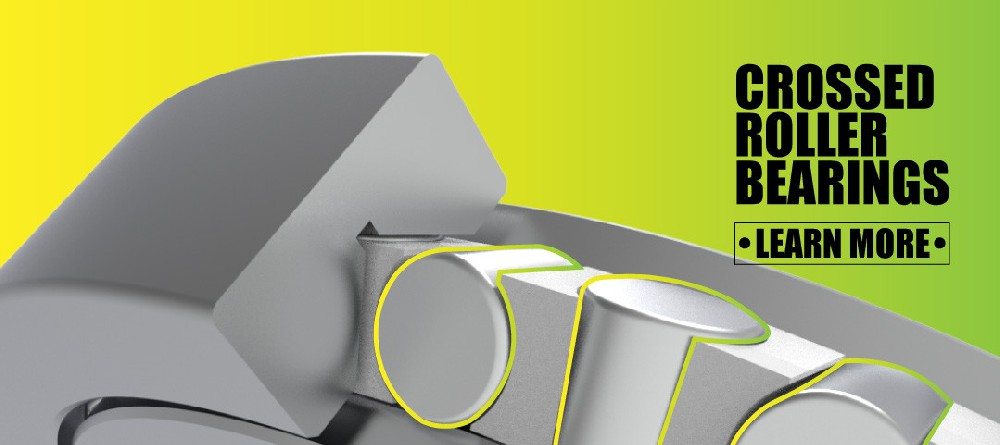
At the heart of a cross roller ring bearing is a 90-degree roller arrangement. Each cylindrical roller sits in a V-shaped groove formed between the inner ring and outer ring, and every roller is oriented at right angles to the next.
When the bearing rotates:
– Radial loads are carried by the rollers aligned in one direction.
– Axial and moment loads are carried by rollers aligned in the perpendicular direction.
– The V-groove raceways guide the rollers and distribute loads evenly, reducing local stress, deformation, and wear.
Because a single row can handle multiple load components, designers can replace multi-bearing stacks with one compact ring that maintains high stiffness, even under complex, combined loads.
Key Design Features Of Cross Roller Rings
Roller Arrangement And Raceway Geometry
A typical cross roller ring includes:
– Cylindrical rollers arranged alternately at 90 degrees.
– Inner and outer rings with precision-ground V-groove raceways.
– Spacer retainers or cages to separate rollers, control friction, and prevent skewing.
This geometry allows the bearing to:
– Support radial, axial, and tilting moment loads simultaneously.
– Achieve running accuracy and repeatable positioning at levels that conventional single-row ball bearings cannot match.
Rigidity And Accuracy
Because the rollers are cross-arranged and the contact pattern is line-contact rather than point-contact, cross roller rings typically exhibit:
– 3–4 times higher rigidity than comparable conventional bearings under similar dimensions.
– Sub-micron repeatability and running accuracy better than 2 µm in advanced designs, when paired with precision machining and correct preload.
For applications like humanoid robots, precision rotary tables, and metrology instruments, this level of stiffness and accuracy is not a luxury—it’s a functional requirement.
Cross Roller Ring vs. Traditional Bearings
Functional Comparison
| Aspect | Cross Roller Ring Bearing | Conventional Ball / Roller Bearing |
|---|---|---|
| Load directions | Radial, axial, tilting moment in one row | Typically one or two load directions per bearing |
| Rigidity | High, often 3–4× higher under equivalent size | Moderate, depends on arrangement |
| Accuracy | Very high rotational accuracy, sub-micron repeatability | Suitable for general motion, limited in ultra-precision |
| Space efficiency | Compact, single ring can replace multi-bearing stacks | Often requires multiple bearings for combined loads |
| Typical use | Robotics joints, precision rotary tables, measuring systems | General machinery, conveyors, low-precision equipment |
| Design complexity | Higher; requires strict alignment and preload control | Lower; more forgiving in assembly |
In practice, engineers choose cross roller rings where precision and stiffness outweigh cost and assembly complexity, and traditional bearings where cost, simplicity, and availability are the primary drivers.
Where Cross Roller Rings Are Used Today
From a designer’s standpoint, cross roller rings appear wherever compact precision rotation is critical. Typical applications include:
– Quadruped robots and humanoid robots: shoulder, elbow, wrist, and hip joints requiring high torque and precise positioning.
– Service, industrial, collaborative, and SCARA robots: each joint must repeat the same trajectory with minimal deflection.
– Exoskeleton and special-purpose robots: human-interactive systems that demand smooth, predictable motion and high safety margins.
– AGV and special vehicles: steering and sensing modules where small misalignment can cascade into navigation errors.
– DD motor rotary tables and hollow rotary platforms: integrating motors and bearings directly in compact footprints.
– CNC machine tools and industrial turntables: indexing tables, 5-axis rotary units, and high-load rotary axes.
– Precision measuring instruments and medical devices: where repeatability and low vibration are essential.
– Radar, communication equipment, and printing/dyeing machinery: requiring continuous stable rotation with combined loads.
From the manufacturing side, we increasingly see robotics and advanced automation projects specify cross roller rings as default for critical joints, while older designs that relied on stacked bearings are gradually being upgraded during redesign cycles.
Types Of Cross Roller Bearings Commonly Used
In real projects, cross roller rings are not a single product but a family of structures tailored to different envelope sizes, load conditions, and installation constraints.
Typical structural types include:
– Standard cross cylindrical roller bearings: for general high-precision rotary applications.
– High-rigidity cross roller bearings: thicker rings and optimized raceways for heavy loads and strong tilting moments.
– Thin-section cross roller bearings: minimal wall thickness for compact robots and lightweight platforms.
– Double-row cross roller bearings: higher load capacity and stiffness for large rotary tables or heavy-duty joints.
– Single-row precision angular contact ball bearings: used alongside cross roller rings where exceptionally high speed or particular axial load patterns are needed.
– High-speed angular contact ball bearings: for spindles and joints with extreme rotational speed requirements.
– Long-life angular contact ball bearings: for continuous duty cycles in automation and special machinery.
By combining these different bearing families, designers can shape the load path inside robots, machine tools, or radar units so that each axis has the necessary stiffness, accuracy, and life expectancy instead of relying on a one-size-fits-all solution.
Practical Working Example: Robot Joint Design
Consider a collaborative robot elbow joint operating on a factory floor:
– The joint must support weight, acceleration, and deceleration, plus off-center payloads that produce tilting moments.
– It must deliver repeatable positioning within tens of microns over thousands of cycles, while remaining compact and safe.
Designers often choose a cross roller ring bearing with appropriate preload, integrated with a hollow shaft or DD motor. In this configuration:
1. Radial loads from the arm structure and payload pass through one set of rollers.
2. Axial loads from vertical motion and braking forces pass through the crossed rollers oriented at 90 degrees.
3. Tilting moments created by off-center payloads are absorbed by the combined contact pattern, minimizing joint deflection.
From field experience, properly selected and installed cross roller rings significantly reduce position drift, vibration, and noise, while extending service life compared with traditional bearing stacks.

How To Select A Cross Roller Ring Bearing
From an engineering and procurement standpoint, selecting the right cross roller ring is a multi-step decision process rather than a single catalog lookup. Below is a practical framework used in many projects:
1. Define Load Cases And Duty Cycles
– Clarify radial, axial, and moment loads, including peak and continuous values.
– Model typical motion profiles: acceleration, deceleration, dwell times, and reversals.
2. Set Target Accuracy And Rigidity
– Specify positioning accuracy and repeatability (for example, ±0.01 mm or better).
– Decide acceptable deflection under full load, especially for robot joints and rotary tables.
3. Determine Space And Integration Constraints
– Evaluate available diameters, widths, and shaft/housing configurations.
– Consider hollow shaft designs for routing cables, pneumatics, or coolant.
4. Select Bearing Type And Preload Level
– Choose between standard, high-rigidity, thin-section, or double-row structures.
– Define preload: light for low friction and speed, higher for stiffness and precision.
5. Assess Environment And Life Requirements
– Consider temperature range, contamination risk, lubrication method, and maintenance intervals.
– Calculate required bearing life based on duty cycle and load spectrum.
6. Verify With Supplier And Prototypes
– Share the full application conditions with bearing manufacturers for technical recommendations.
– Test prototypes in the actual equipment, measuring torque, accuracy, and thermal behavior.
Working through these steps with a specialized manufacturer allows you to move from catalog-level selection to a robust, application-specific configuration.
Installation And Preload: Lessons From The Field
Even a perfect bearing design can fail to deliver its theoretical performance if installation and preload are not handled correctly. Common best practices include:
– Machining precision mating surfaces: The housing and shaft shoulders must be flat, concentric, and free from burrs.
– Controlled tightening sequence: Tighten mounting bolts gradually in crosses rather than sequentially, avoiding ring distortion.
– Correct preload: Too little preload results in backlash and reduced stiffness; too much preload increases torque, heat, and wear.
– Cleanliness and lubrication: Foreign particles and improper lubrication are leading causes of premature failure.
– Verification tests: After installation, measure rotational torque, runout, and temperature rise during trial runs.
In high-precision applications like medical imaging or metrology, it is common to perform laser interferometer or encoder-based verification to confirm that the installed bearing meets the positioning and repeatability targets.
When To Combine Cross Roller Rings With Angular Contact Bearings
In many systems, cross roller rings are used together with angular contact ball bearings to balance speed, life, and stiffness.
Typical scenarios:
– High-speed spindles or rotary axes: cross roller rings may handle combined loads close to the tool or workpiece, while angular contact bearings manage very high-speed conditions elsewhere.
– Multi-axis robotics platforms: critical axes (shoulders, base, main rotary table) use cross roller rings, while secondary axes rely on angular contact bearings optimized for speed and noise.
– Precision reducers (harmonic and planetary): cross roller rings form the output bearings, and angular contact bearings are integrated into input or intermediate shafts.
By carefully coordinating these bearing types, designers can create balanced systems that maintain precision where it matters most, while still delivering the required speed and durability.
Why Many Designers Prefer Cross Roller Rings
From conversations with robotics engineers, machine tool builders, and instrumentation designers, several recurring reasons explain why cross roller rings are chosen over alternatives:
– Compact integration: one ring handles multiple load components without extra bearing stacks.
– High stiffness: critical for dynamic performance, vibration control, and trajectory accuracy.
– Predictable behavior under preload: essential for high-performance servo control.
– Long-term repeatability: the ability to maintain accuracy over extended cycles with proper lubrication and alignment.
– Design flexibility: hollow shafts, integrated rotary platforms, and direct motor coupling become more practical.
For equipment builders, this often translates into simpler mechanical layouts, fewer components, and a higher probability of meeting demanding performance specifications.
How A Professional Bearing Manufacturer Can Help
For OEMs and integrators, working directly with a specialized bearing manufacturer brings tangible advantages:
– Application-driven design support: guidance on bearing selection, raceway geometry, and preload schemes.
– Customized structures: thin-wall, high-rigidity, double-row, or special-profile rings tailored to robots, radar vehicles, medical devices, or precision platforms.
– Co-development with research institutes: validation through dedicated test rigs and joint research projects.
– Stable quality and cost-performance: consistent production processes that deliver reliable performance at competitive pricing.
As your equipment evolves—toward heavier payloads, higher speeds, or tighter accuracy requirements—this partnership allows you to upgrade bearing configurations without redesigning the entire mechanical system from scratch.

Action-Oriented Guidance For Engineers And Buyers
If you are planning or upgrading a project that involves precision rotary motion:
– Review your current axes where position accuracy, stiffness, or compactness are limiting performance.
– Identify joints or rotary stages that would benefit from multi-directional load capability and single-ring integration.
– Engage with a bearing manufacturer capable of providing precision cross roller rings and high-precision angular contact bearings, plus technical support on preload, lubrication, and installation.
By treating bearing selection as an early design decision, not a late procurement step, you can significantly improve the reliability, performance, and lifecycle cost of your robots, machine tools, and advanced equipment.
If your quadruped robot, collaborative robot, radar platform, or precision rotary table is approaching its next design iteration, now is the right time to evaluate whether cross roller ring bearings and high-precision angular contact ball bearings can unlock the performance you are targeting.
Discuss your load cases, accuracy targets, and space constraints with an experienced bearing manufacturer, request sample configurations, and validate them in your prototype line. Turning rotary precision into a strategic design asset rather than a last-minute compromise is often the difference between a good product and a category-leading one.
Frequently Asked Questions
Q1: What makes a cross roller ring different from a standard ball bearing?
A cross roller ring uses cylindrical rollers arranged at right angles in a single raceway, allowing it to carry radial, axial, and tilting moment loads simultaneously with higher stiffness and accuracy than typical single-row ball bearings.
Q2: Can cross roller rings replace multiple bearings in a robot joint?
Yes. In many robot joints, a single well-selected cross roller ring can replace stacked bearings used for separate radial and axial loads, simplifying design and improving stiffness and repeatability, provided the bearing is correctly sized and preloaded.
Q3: Are cross roller rings suitable for high-speed applications?
They can operate at significant speeds, but their primary strength is stiffness and accuracy under combined loads. For extremely high-speed spindles, angular contact ball bearings may still be preferred for specific axes, sometimes combined with cross roller rings in the same system.
Q4: What are typical mistakes when installing cross roller rings?
Common issues include poor surface preparation, uneven bolt tightening that distorts the rings, incorrect preload (too tight or too loose), contamination, and inadequate lubrication, all of which can degrade theoretical performance and shorten service life.
Q5: How do cross roller rings contribute to robot safety and reliability?
By providing high stiffness, predictable behavior under preload, and stable long-term accuracy, cross roller rings help reduce unexpected position errors, vibration, and mechanical play, which in turn enhances the safety, reliability, and service life of robots and other precision equipment.
References
1. THK – “Cross Roller Ring” – detailed description of cross roller ring structure and load capacity.
[https://www.thk.com/eu/en/products/cross_roller_ring/cross_roller_ring/] [thk]
2. LKPBearing – “What’s A Cross Roller Ring Bearing And How Does It Work?” – introductory overview of working principle and structure.
[https://lkpbearing.com/whats-a-cross-roller-ring-bearing-and-how-does-it-work/] [lkpbearing]
3. Slewing-Bearing.com – “What are the differences between cross roller bearings and slewing ring bearings?” – comparison of rigidity and load capacity.
[https://www.slewing-bearing.com/what-are-the-differences-between-cross-roller-bearings-and-slewing-ring-bearings/] [slewing-bearing]
4. Patsnap Eureka Report – “Cross-Roller Bearings for Robot Arms: Achieving Positional Accuracy” – advanced precision metrics and design considerations for robotics applications.
[https://eureka.patsnap.com/report-cross-roller-bearings-for-robot-arms-achieving-positional-accuracy] [eureka.patsnap]
5. CCTY Group – “How Cross Roller Bearings Maximize Precision & Performance” – application examples in complex robotic systems and design insights.
[https://cctygroup.com/how-cross-roller-bearings-maximize-precision-performance/] [cctygroup]
6. LKPBearing – “Crossed Roller Bearing Applications: A Comprehensive Overview” – practical applications in robotics, automation, and precision equipment.
[https://lkpbearing.com/crossed-roller-bearing-applications-a-comprehensive-overview/] [lkpbearing]
7. SLC Bearings – “What are the typical applications of cross roller bearings?” – usage in robots, inspection platforms, and industrial equipment.
[https://www.slcbearings.com/detailsc/139.html] [slcbearings]
8. SKF / Machine Design – “Why Crossed Roller Bearings Dominate Precision Robotics and Automation” – industry insights into stiffness and tipping moment resistance.
[https://www.machinedesign.com/mechanical-motion-systems/video/55376218/skf-usa-why-crossed-roller-bearings-dominate-precision-robotics-and-automation] [machinedesign]
9. Hiwin – “Crossed Roller Bearings” (Video) – visual explanation of roller and spacer arrangement.
[https://www.youtube.com/watch?v=eEBXNMyjwVo] [youtube]
10. Yuwei Bearing – “What Does Yuwei Bearing Offer? Products & Selling Points” – overview of precision cross roller bearings and angular contact ball bearing series.
[https://yuwei-bearing.com/zh/yuwei-bearing-offer-products-selling-points/] [yuwei-bearing]
Hot Tags: Cross Roller Ring Bearing, Precision Cross Roller Bearing, High Rigidity Cross Roller Bearing, Thin Section Cross Roller Bearing, Double Row Cross Roller Bearing, Angular Contact Ball Bearing, Robot Joint Bearing, Rotary Table Bearing, DD Motor Bearing, Precision Robotics Bearing