Content Menu
● What Are Crossed Roller Bearings?
● Load Capacity, Rigidity, and Precision Compared
● Speed, Torque, and Thermal Behavior
● Market Data and Industry Momentum
● Field Application: Robotics and Special-Purpose Platforms
● How to Choose: A Practical Selection Framework
Choosing between roller bearings and crossed roller bearings is one of the most consequential decisions a mechanical or robotics engineer will make during component selection. The wrong choice quietly erodes positioning accuracy, shortens service life, or adds unnecessary cost to a bill of materials. This guide breaks down the structural, performance, and application differences between standard roller bearings and crossed roller bearings, drawing on current market data, field engineering commentary, and manufacturing experience from precision bearing production for robotics, radar systems, and machine tools.
As a manufacturer that engineers precision crossed roller bearings and angular contact ball bearings for humanoid robots, collaborative robots, AGVs, and radar platforms, we see this comparison come up constantly from design engineers sourcing components for next-generation automation. Below is a practical, technically grounded breakdown.

What Are Roller Bearings?
Roller bearings are rolling-element bearings that use cylindrical, tapered, or spherical rollers instead of balls to support a load. Because the rollers make line contact with the raceway rather than the point contact of a ball, they spread force across a larger surface area.
Common roller bearing subtypes include:
– Cylindrical roller bearings – handle heavy radial loads, common in gearboxes and electric motors.
– Tapered roller bearings – manage combined radial and axial loads, widely used in automotive wheel hubs.
– Spherical roller bearings – self-aligning, used where shaft misalignment is expected.
– Needle roller bearings – compact, high radial load capacity in tight spaces.
These bearings excel in heavy-duty, high-load environments such as gearboxes, conveyors, and wind turbine drivetrains, but they were never designed for precision positioning tasks.
What Are Crossed Roller Bearings?
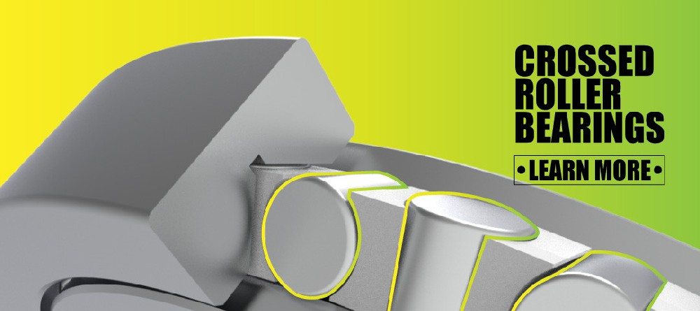
Crossed roller bearings are a specialized rolling-element design in which cylindrical rollers are arranged alternately at 90-degree angles to one another between a single inner ring and outer ring (or split-ring variants). This orthogonal roller arrangement is the single most important structural distinction in the roller bearings vs. crossed roller bearings comparison.
Because alternating rollers each carry load in a different direction, one crossed roller bearing can replace two angular contact ball bearings arranged back-to-back, while occupying a fraction of the axial space. This is why crossed roller bearings dominate compact, high-precision assemblies like:
– Robot joints (SCARA, six-axis, collaborative, and humanoid robots)
– Rotary tables and machining center indexing units
– Harmonic and planetary reducer output stages
– Radar antenna pedestals and rotating communication platforms
– Medical imaging gantries and surgical robot arms
Common structural variants include standard crossed roller bearings, split inner/outer ring designs for easier installation, thin-section (thin-wall) crossed roller bearings for weight-sensitive robotics, and double-row crossed roller bearings for combined heavy radial, axial, and moment loading.
Core Structural Differences
The performance gap between these two bearing families comes down to geometry. The table below summarizes the practical differences engineers evaluate during selection.
| Characteristic | Roller Bearings | Crossed Roller Bearings |
|---|---|---|
| Rolling element arrangement | Parallel, single direction | Alternating rollers at 90° |
| Load directions handled | Primarily radial (some axial) | Radial, axial, and moment loads simultaneously |
| Rigidity | Moderate to high | 3 to 4 times higher than equivalent ball bearings |
| Precision class | Standard to precision grades | High precision (P5, P4, P2 grades common) |
| Axial footprint | Larger, often needs paired bearings | Compact, single-row replaces two ball bearings |
| Speed capability | Lower, higher friction at speed | Higher, due to alternating contact geometry |
| Typical cost | Lower | Higher, due to grinding and assembly complexity |
| Best-fit environment | Heavy machinery, gearboxes, high-load rotation | Robotics, rotary tables, radar, medical devices |

Load Capacity, Rigidity, and Precision Compared
Standard roller bearings win on raw radial load capacity because their rollers align in one direction and the raceway can be optimized purely for that load path. This makes them the correct choice for gearboxes, heavy rotating shafts, and industrial drivetrains where axial precision is secondary to sheer load-bearing volume.
Crossed roller bearings, however, are engineered for a different priority: simultaneous multi-directional accuracy. Because rollers contact four raceway surfaces instead of two, a crossed roller bearing resists tipping moments far better than a comparable roller or ball bearing. Industry engineers report rigidity three to four times greater than a double-row angular contact ball bearing occupying similar space, since roller clearance can even be set to negative preload to eliminate internal play entirely.
This rigidity advantage is precisely why a robotic arm using crossed roller bearings in its joints can place a component within microns repeatedly, cycle after cycle, without measurable drift.
Speed, Torque, and Thermal Behavior
Engineers frequently ask which bearing type runs cooler and faster. The honest answer depends on the load regime:
– Roller bearings generate more friction at high rotational speed because larger, uniformly-aligned rollers create more rolling resistance under sustained radial load.
– Crossed roller bearings typically run warmer than ball bearings at a given speed because roller-to-race contact area is larger, which increases lubricant shear. Design engineers must select lubricants rated for the additional heat and monitor lube degradation more closely in continuous-duty applications.
– Starting torque is higher for crossed roller bearings than for ball bearings of similar size, meaning initial rotation feels “tighter,” though accuracy remains stable even after millions of cycles.
For intermittent, high-precision motion — the profile of most robot joints and rotary tables — this thermal trade-off is manageable and vastly outweighed by the accuracy gained.
Market Data and Industry Momentum
The global bearing landscape reflects a clear structural shift toward precision components. According to market research, the cross roller bearings market is valued at approximately USD 1.5 billion in 2024 and is projected to reach USD 1.9 billion by 2031, growing at a compound annual rate near 3.2 percent, driven overwhelmingly by robotics, aerospace, and automated manufacturing demand.
Separately, industry reporting on the broader precision segment shows high-rigidity crossed roller bearings as the fastest-growing product category within this space, and forecasts single out robotics, semiconductor manufacturing equipment, and medical systems as the three verticals absorbing the largest share of new demand. The International Federation of Robotics has also tracked global industrial robot shipments climbing from roughly 254,000 units in 2015 to 384,000 units by 2018, a trajectory that has only accelerated with the rise of humanoid and collaborative robot platforms — every joint in these machines requires a compact, high-rigidity bearing solution.
This is not an abstract trend. It directly explains why bearing manufacturers are now investing specifically in thin-section and double-row crossed roller designs: robot builders need lighter, flatter joints without sacrificing stiffness, and standard roller or ball bearings simply cannot deliver that combination.
Field Application: Robotics and Special-Purpose Platforms
In practice, the choice between these two bearing families becomes obvious once you map it to a real mechanical assembly. Consider three application families where the distinction matters most:
1. Quadruped and humanoid robot joints — Each joint must support radial load from the limb, axial load from gravity, and resist tipping moments during dynamic movement, all within a housing only millimeters thick. Crossed roller bearings, particularly thin-wall variants, are the only practical structural solution.
2. Radar and communication pedestals — Rotating radar platforms need a bearing that holds angular position precisely while supporting the antenna’s weight and wind-induced moment loads. Large-bore crossed roller bearings, often developed jointly with research institutions for specialized defense and telecommunications equipment, handle this reliably in continuous outdoor duty.
3. Machine tool rotary tables and hollow rotary platforms — Positioning accuracy in a CNC rotary table depends on eliminating clearance under cutting load. Split-ring crossed roller bearings, adjusted for slight negative clearance, hold repeatable accuracy through thousands of indexing cycles.
Through joint research and trial programs with technical universities and institutes, bearing developers have iterated on these exact configurations for specialized robots, radar vehicles, and other purpose-built platforms — validating designs under real dynamic load and moment conditions rather than theoretical ratings alone.

How to Choose: A Practical Selection Framework
Use this sequence when specifying a bearing for a new mechanical design:
1. Define the dominant load type. If the assembly experiences primarily one-directional radial load (a gearbox shaft, a conveyor roller), a standard roller bearing is usually more cost-effective.
2. Check for combined or moment loading. If the design must resist tipping, misalignment, or simultaneous radial and axial forces in a tight envelope, move to crossed roller bearings.
3. Set your precision requirement. Applications needing repeatable positioning within microns (robot joints, rotary tables, optical instruments) require crossed roller bearings rated P5 or higher.
4. Evaluate available space. If axial length is constrained, remember one crossed roller bearing can replace two angular contact ball bearings, saving both space and mounting complexity.
5. Confirm speed and thermal profile. For continuous high-speed rotation with lower moment demands, a standard roller or ball bearing may run cooler and last longer.
6. Validate with the manufacturer. Confirm preload, sealing, and lubrication specifications against your actual duty cycle rather than relying on catalog defaults alone.
Expert Perspective
Bearing selection mistakes rarely show up immediately. They surface months later as unexplained backlash, premature wear, or accuracy drift in a robot arm that “used to be precise.” In our own engineering practice supplying precision crossed roller bearings and high-precision angular contact ball bearings to robotics and instrumentation manufacturers, the recurring lesson is this: specify for the moment load, not just the radial number on the datasheet. A bearing rated adequately for radial force can still fail structurally under tipping moments that a spec sheet doesn’t emphasize. This is precisely the failure mode crossed roller bearings were engineered to eliminate.
Final Recommendation
Roller bearings remain the pragmatic, cost-efficient choice for heavy, single-direction radial loads in general industrial machinery. Crossed roller bearings are the necessary choice wherever compact, multi-directional rigidity and repeatable precision define success — robotics, rotary tables, radar systems, and precision instrumentation.
If your project involves robotic joints, rotary platforms, radar pedestals, or any application demanding both stiffness and space efficiency, consult a precision bearing engineering team before finalizing your design. Share your load conditions, envelope dimensions, and duty cycle, and a qualified supplier can recommend the correct series, precision grade, and preload configuration for your specific mechanism — request a technical consultation today.
Frequently Asked Questions
1. Can a crossed roller bearing simply replace a standard roller bearing in an existing design?
Not automatically. Crossed roller bearings usually have a different mounting profile and often require a solid or split housing with bolt-hole patterns rather than a simple bore fit. A mechanical redesign of the mounting interface is typically required.
2. Which bearing type is better for high-speed spindles?
Neither is the default choice — high-speed spindles usually use angular contact ball bearings. Crossed roller bearings suit high-precision, moderate-speed rotary motion rather than very high rotational speed spindle applications.
3. Are crossed roller bearings more expensive than standard roller bearings?
Yes. The alternating roller geometry, tighter grinding tolerances, and precision-grade manufacturing raise production cost. The added expense is justified when rigidity, compactness, and multi-directional accuracy are required.
4. What precision grades are typically used in robotics applications?
Robot joints and rotary tables commonly specify P5 or P4 grade crossed roller bearings, with P2 reserved for ultra-precision instrumentation and specialized research equipment.
5. Do crossed roller bearings need special lubrication?
Generally yes. Because roller-to-race contact area is larger and starting torque is higher, lubricants must be selected for higher shear tolerance and heat resistance compared to standard ball bearing grease.
6. Can crossed roller bearings handle both radial and axial loads simultaneously?
Yes — this is their defining advantage. The 90-degree alternating roller arrangement allows a single-row crossed roller bearing to manage radial, axial, and moment loads at once, something a standard roller bearing cannot do without a paired bearing arrangement.
References
– Persistence Market Research, “Cross Roller Bearings Market Size & Share Analysis” — [persistencemarketresearch.com]
– Fortune Business Insights, “Cross Roller Bearings Market Size, Share, Potential, Growth 2032” — [fortunebusinessinsights.com]
– Machine Design, “Why Crossed Roller Bearings Dominate Precision Robotics and Automation” (SKF engineering interview) — [machinedesign.com]
– RIGB RS Bearing, “Compare from Six Aspects – Crossed Roller Vs Ball Bearing” — [rigbrsbearing.com]
– LKP Bearing, “Roller Bearings Vs. Crossed Roller Bearings: Understanding The Differences” — [lkpbearing.com]
Hot Tags: Crossed Roller Bearings, Precision Roller Bearings, Angular Contact Ball Bearings, Thin Section Crossed Roller Bearings, High Rigidity Bearings, Robotic Joint Bearings, Rotary Table Bearings, CNC Machine Tool Bearings, Bearing Manufacturer China, Industrial Robot Bearings