Content Menu
● What Is the Main Difference Between a Cross Roller Bearing and a Ball Bearing?
>> Cross Roller Bearing Structure
● Cross Roller Bearing vs Ball Bearing Comparison Table
● Why Cross Roller Bearings Deliver Higher Rigidity
>> 1. Larger Load-Carrying Contact Area
>> 2. Alternating 90-Degree Roller Arrangement
>> 3. High Moment Rigidity in Compact Designs
● When an Angular Contact Ball Bearing Is Better
>> Lower Friction and Starting Torque
>> Easier Procurement and Lower Initial Cost
● High Rigidity Application Comparison
● Practical Selection Process for Engineers
>> 1. Define All Load Directions
>> 2. Calculate Allowable Deflection
>> 3. Review Mounting Surface Accuracy
>> 4. Consider Rotational Speed and Heat
>> 5. Choose the Right Accuracy Grade
● Expert Insight: System Rigidity Matters More Than Bearing Rigidity Alone
● Cross Roller Bearing Advantages for Robotics and Precision Equipment
● Common Buying Mistakes to Avoid
>> Mistake 1: Comparing Only Static Load Rating
>> Mistake 2: Ignoring Moment Load
>> Mistake 3: Selecting Excessive Preload
>> Mistake 4: Using Inadequate Mounting Components
>> Mistake 5: Choosing a Standard Design for a Specialized Load Case
● Final Verdict: Which Bearing Is Better for High Rigidity?
● FAQs
>> 1. Are cross roller bearings more rigid than ball bearings?
>> 2. Can a cross roller bearing replace two angular contact ball bearings?
>> 3. Are cross roller bearings suitable for high-speed rotation?
>> 4. Why are cross roller bearings commonly used in robots?
>> 6. How does preload affect bearing rigidity?
>> 7. What information should I provide when requesting a bearing quotation?
When engineers compare a cross roller bearing vs ball bearing for a high-rigidity application, the right choice depends on more than load capacity alone. Rotational accuracy, overturning moment, installation space, speed, preload, lubrication, housing stiffness, and expected service life all affect the final performance of the system.
For applications where high rigidity, low deflection, compact installation, and multi-directional load support are critical, a precision cross roller bearing is usually the stronger option. For high-speed shafts, lower friction, simpler arrangements, and cost-sensitive equipment, angular contact ball bearings may provide a better overall engineering balance.
Henan Yuwei Industrial Technology Co., Ltd. manufactures precision cross roller bearings and high-precision angular contact ball bearings for robotic joints, machine tools, rotary tables, medical devices, radar equipment, harmonic reducers, DD motors, AGVs, and precision automation systems. This article explains the practical differences between these two bearing solutions and helps design teams select the right structure for high-rigidity applications.

What Is the Main Difference Between a Cross Roller Bearing and a Ball Bearing?
The most important difference between a cross roller bearing and a ball bearing is the geometry of the rolling elements.
A conventional ball bearing uses spherical balls that contact the raceways over a relatively small contact area. An angular contact ball bearing uses a defined contact angle to support combined radial and axial loads. It is widely used in machine-tool spindles, motor shafts, pumps, high-speed equipment, and precision transmission assemblies.
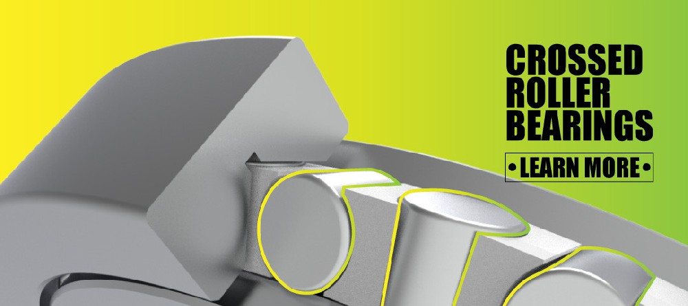
A cross roller bearing uses cylindrical rollers arranged alternately at 90 degrees. One roller is oriented in one direction, while the adjacent roller is perpendicular to it. This crossed arrangement allows a single bearing to withstand radial load, axial load, and overturning moment load simultaneously.
Because cylindrical rollers create line contact with the raceways, cross roller bearings generally provide higher stiffness than ball bearings of comparable size. Roller bearings also tend to distribute load across a larger contact area than point-contact ball bearing designs. Schaeffler notes that bearing stiffness depends on factors such as bearing type, size, clearance, and the number of loaded rolling elements, while line-contact roller designs generally have higher rigidity than ball bearing designs.
Cross Roller Bearing Structure
A precision cross roller bearing usually includes:
– An inner ring and outer ring
– Cylindrical rollers arranged alternately at 90 degrees
– A cage or spacer retainer between rollers
– Precision raceways designed for preload or controlled clearance
– High-accuracy mounting surfaces
– Sealing, lubrication, or corrosion-protection options depending on the environment
This configuration allows one compact bearing to manage complex loads that would otherwise require two or more conventional bearing sets.
Ball Bearing Structure
A ball bearing typically includes:
– An inner ring and outer ring
– Steel or ceramic balls
– A cage that separates the balls
– Raceways designed for radial, axial, or combined loads
– Optional contact seals, shields, or lubrication systems
For high-precision equipment, angular contact ball bearings are often mounted in pairs, triples, or quadruplex arrangements. Common arrangements include back-to-back, face-to-face, and tandem configurations.
Cross Roller Bearing vs Ball Bearing Comparison Table
The table below summarizes the major differences between a precision cross roller bearing and a high-precision angular contact ball bearing.
| Comparison Factor | Cross Roller Bearing | Angular Contact Ball Bearing |
|---|---|---|
| Rolling element | Cylindrical rollers | Balls |
| Contact geometry | Line contact | Point contact |
| Primary advantage | High rigidity and moment capacity | High speed and low friction |
| Radial load support | Excellent | Good to excellent, depending on design |
| Axial load support | Supports axial loads in both directions in one unit | Often requires paired bearings for bidirectional axial loads |
| Moment load capacity | Excellent | Moderate; improved with paired arrangements |
| Rotational rigidity | Very high | Moderate to high |
| Deflection under load | Usually lower | Usually higher under equivalent load and size conditions |
| Installation space | Compact for combined-load applications | May need multiple bearings and additional spacing |
| High-speed suitability | Moderate; design-dependent | Excellent, especially with optimized preload and lubrication |
| Sensitivity to mounting accuracy | High | Moderate to high |
| Typical applications | Robot joints, rotary tables, radar, reducers, measuring instruments | Spindles, motors, pumps, gearboxes, compressors, high-speed shafts |
| Cost structure | Higher unit cost, but may reduce system complexity | Often economical, especially for standard arrangements |
Neither bearing type is universally “better.” The correct choice depends on the operating condition and the system-level design target.

Why Cross Roller Bearings Deliver Higher Rigidity
For high-rigidity rotating mechanisms, the key requirement is not only supporting the load. The bearing must also resist elastic deformation, axial displacement, tilt, and runout.
Cross roller bearings are highly effective because their rollers are arranged in alternating directions. This layout enables the bearing to support loads from multiple directions without requiring a separate bearing pair.
THK describes cross-roller rings as bearings in which cylindrical rollers are arranged orthogonally in a 90-degree V-groove. The design allows one bearing to receive radial, axial, and moment loads in all directions.
1. Larger Load-Carrying Contact Area
A cylindrical roller contacts the raceway along a line rather than at a small point. This creates a larger effective contact zone and helps reduce local stress concentration.
In practical terms, this means a cross roller bearing can resist deformation more effectively when the equipment experiences:
– Heavy radial force
– Axial thrust in either direction
– Tilting moment
– Repeated positioning loads
– Variable robotic arm loads
– Eccentric payloads
– Shock loads during starts and stops
For a robot joint, for example, the load is rarely perfectly centered. The arm length, end effector, workpiece, acceleration, and gravity create continuous overturning moment. A cross roller bearing is designed to manage this type of combined load efficiently.
2. Alternating 90-Degree Roller Arrangement
The alternating roller orientation is the defining advantage of a cross roller bearing. Rollers facing one direction can support one load component, while rollers oriented at 90 degrees support another.
This design improves resistance to:
– Axial movement
– Radial movement
– Rotational tilting
– Moment load
– Structural wobble
– Positioning error
For compact robot joints, hollow rotary platforms, and harmonic reducer output stages, this is particularly valuable because the bearing must often carry multiple load directions in a limited space.
3. High Moment Rigidity in Compact Designs
Moment rigidity is essential when a rotating component supports a load at a distance from the bearing centerline.
Consider a robotic arm with a payload attached 400 mm away from the joint center. Even a moderate payload can create a significant moment load. If the bearing deflects, the end effector position can shift, reducing repeatability and affecting welding, assembly, inspection, dispensing, or material-handling accuracy.
A cross roller bearing can often replace a more complicated system using paired angular contact ball bearings, spacer rings, and additional support components. This can reduce axial stack height and simplify assembly.
THK states that certain cross-roller ring structures can achieve rigidity approximately three to four times greater than conventional thin angular contact ball bearing arrangements, depending on the design and comparison conditions.
When an Angular Contact Ball Bearing Is Better
Although cross roller bearings are often preferred for high-rigidity applications, angular contact ball bearings remain the better option in many situations.
The decision becomes clearer when the application prioritizes rotational speed, low torque, thermal control, and lower system cost over maximum moment rigidity.
High-Speed Operation
Angular contact ball bearings are commonly used in high-speed precision equipment because balls generate lower rolling friction than cylindrical rollers in many operating conditions.
They are widely used in:
– CNC machine-tool spindles
– Grinding spindles
– High-speed electric motors
– Turbochargers
– Centrifugal pumps
– Compressors
– High-speed gearbox shafts
– Precision machining centers
SKF notes that angular contact ball bearings have raceways that are displaced relative to each other in the axial direction, allowing them to support combined radial and axial loading.
For high-speed spindle systems, designers can use optimized bearing arrangements, controlled preload, high-performance lubricants, ceramic balls, and cooling strategies to achieve high rotational accuracy and stable temperature performance.
Lower Friction and Starting Torque
Ball bearings are often preferred when low torque is important. Lower friction can support:
– Faster acceleration
– Reduced energy consumption
– Lower heat generation
– Improved motor efficiency
– Easier manual rotation
– Smoother motion in light-load mechanisms
This makes angular contact ball bearings suitable for equipment where the load is relatively controlled and speed is more important than high moment capacity.
Easier Procurement and Lower Initial Cost
Standard angular contact ball bearings are widely available in many bore sizes, contact angles, precision grades, cage materials, and preload classes.
For applications without extreme rigidity requirements, they may provide a more economical solution. However, engineers should consider the total system cost rather than the bearing purchase price alone.
A lower-cost bearing arrangement may require:
– Two or more bearings
– Spacer rings
– Complex preload adjustment
– Larger housings
– Additional mounting components
– More assembly time
– Increased tolerance management
A cross roller bearing may cost more per unit but reduce component count and simplify the overall design.
High Rigidity Application Comparison
The table below helps designers determine which bearing type is generally better for common precision applications.
| Application | Recommended Bearing Type | Why |
|---|---|---|
| Industrial robot joint | Cross roller bearing | High moment rigidity, compact installation, combined load support |
| Humanoid robot joint | Cross roller bearing | High precision under variable and eccentric loading |
| Harmonic reducer output | Cross roller bearing | Strong resistance to tilting and high torque loads |
| DD motor rotary axis | Cross roller bearing | High rotational accuracy and moment capacity |
| CNC rotary table | Cross roller bearing | Supports radial, axial, and moment loads in a compact structure |
| Machine-tool spindle | Angular contact ball bearing | Better high-speed performance and thermal behavior |
| High-speed electric motor | Angular contact ball bearing | Lower friction and efficient high-speed rotation |
| Medical imaging rotary unit | Cross roller bearing or angular contact ball bearing | Depends on payload, speed, smoothness, and space constraints |
| Precision measuring instrument | Cross roller bearing | Low runout and strong resistance to external disturbance |
| Light-duty automation shaft | Angular contact ball bearing | Cost-effective and suitable for high-speed light-load rotation |
Practical Selection Process for Engineers
Selecting the right bearing should begin with the real operating condition, not simply the catalog load rating.
A good bearing selection process includes the following steps.
1. Define All Load Directions
Do not evaluate radial load alone. Identify:
– Radial load
– Axial load
– Reversing axial load
– Moment load
– Shock load
– Dynamic load during acceleration
– Emergency-stop load
– Eccentric payload load
If radial, axial, and moment loads act at the same time, a cross roller bearing should be evaluated early in the design process.
2. Calculate Allowable Deflection
Load capacity is not the same as stiffness.
A bearing may safely support a load without failing, but the machine may still lose accuracy if the bearing deflects too much. For precision robotic joints, measurement equipment, radar platforms, and machine-tool rotary axes, allowable displacement may be far more important than basic load rating.
Ask the following questions:
– What is the maximum allowable axial movement?
– What is the allowable radial displacement?
– What is the acceptable angular tilt?
– How much positioning error can the final mechanism tolerate?
– Will deflection affect product quality or process stability?
3. Review Mounting Surface Accuracy
A high-rigidity bearing cannot compensate for a poor housing or shaft interface.
Cross roller bearings are especially sensitive to mounting flatness, perpendicularity, bolt tightening sequence, and housing rigidity. A rigid bearing installed on a flexible mounting structure will not deliver its expected performance.
Crossed roller bearing guidance from NB Corporation notes that these designs can be less forgiving of mounting-surface inaccuracies due to their rigidity and construction.
For best results:
– Machine mounting shoulders accurately
– Control surface flatness and perpendicularity
– Use appropriate mounting bolts and tightening torque
– Follow a cross-pattern tightening sequence
– Avoid uneven clamping force
– Verify shaft and housing fits
– Maintain cleanliness during installation
4. Consider Rotational Speed and Heat
If the application runs continuously at high speed, thermal behavior becomes a critical design factor.
Higher preload generally increases rigidity, but it can also increase friction and heat generation. This applies to both cross roller bearings and angular contact ball bearings.
SKF explains that preload in super-precision angular contact ball bearing arrangements is commonly achieved by adjusting the axial position of the bearing rings relative to each other.
The engineering challenge is to balance:
– Rigidity
– Friction torque
– Temperature rise
– Lubricant performance
– Rotational speed
– Service life
– Noise and vibration
5. Choose the Right Accuracy Grade
Bearing precision should match the equipment requirement.
For high-precision rotary systems, evaluate:
– Radial runout
– Axial runout
– Rotational torque variation
– Raceway geometry
– Preload consistency
– Cage quality
– Surface finish
– Ring material stability
– Heat-treatment quality
A high-precision cross roller bearing can improve positioning consistency in industrial robots, rotary tables, and measurement instruments. A high-precision angular contact ball bearing can improve spindle accuracy and high-speed stability.
Expert Insight: System Rigidity Matters More Than Bearing Rigidity Alone
One common design mistake is selecting the highest-rigidity bearing available while ignoring the surrounding structure.
The effective stiffness of a rotary assembly depends on the complete load path:
Ksystem=f(Kbearing,Kshaft,Khousing,Kmounting,Kfasteners)
In simple terms, a cross roller bearing cannot fully improve machine precision if the shaft bends, the housing wall is too thin, the flange is not flat, or the mounting bolts lose preload.
For example, a robot joint may use a high-rigidity cross roller bearing, but its end-effector accuracy can still suffer if:
– The reducer housing flexes under torque
– The bearing seat is not machined correctly
– The bolt circle is too small
– The support flange is too thin
– Assembly contamination damages the raceway
– The joint experiences unexpected impact loading
The best approach is to evaluate the bearing together with the shaft, housing, reducer, flange, fasteners, and load direction.
Cross Roller Bearing Advantages for Robotics and Precision Equipment
Cross roller bearings have become increasingly important in advanced automation because modern robotic systems demand compactness, repeatability, and high load resistance.
They are especially suitable for:
– Four-legged robots
– Service robots
– Industrial robots
– Collaborative robots
– SCARA robots
– Medical robots
– Exoskeleton robots
– Humanoid robots
– Special-purpose robots
– AGV steering and rotating modules
– Radar rotation platforms
– Precision medical equipment
– CNC machine-tool rotary tables
– Hollow rotary platforms
– Harmonic reducers
– Planetary reducers
– DD motor systems
For these applications, a cross roller bearing can provide several benefits:
– High rigidity under radial, axial, and moment loads
– Compact structure that helps reduce equipment size
– High rotational accuracy for positioning and repeatability
– Simplified design because one bearing can carry multiple loads
– Stable motion under changing load direction
– Suitable preload control for precision applications
– Strong support for eccentric loads common in robot arms and rotary mechanisms
Henan Yuwei Industrial Technology Co., Ltd. supplies precision cross cylindrical roller bearings, high-rigidity cross roller bearings, thin-section cross roller bearings, double-row cross roller bearings, high-precision angular contact ball bearings, high-speed angular contact ball bearings, and long-life angular contact ball bearing solutions for these demanding operating environments.

Common Buying Mistakes to Avoid
When sourcing a cross roller bearing or angular contact ball bearing, avoid making decisions based only on outside diameter, bore size, or price.
Mistake 1: Comparing Only Static Load Rating
Static load rating does not show how much a bearing will deflect during operation. For high-rigidity equipment, request stiffness data, preload information, rotational accuracy specifications, and permissible moment load values.
Mistake 2: Ignoring Moment Load
A bearing may have sufficient radial and axial capacity but still fail to meet accuracy requirements under tilting moment. This is common in robot joints, camera platforms, inspection equipment, and rotary tables.
Mistake 3: Selecting Excessive Preload
More preload does not always mean better performance. Excessive preload can increase friction, heat, wear, and torque fluctuation.
Mistake 4: Using Inadequate Mounting Components
High-quality bearings require accurate shafts, housings, mounting surfaces, bolts, and assembly practices. Poor installation can reduce bearing life and rotational accuracy.
Mistake 5: Choosing a Standard Design for a Specialized Load Case
Custom applications may require special dimensions, preload levels, grease types, sealing structures, anti-corrosion treatment, cage materials, or accuracy grades.
Working with a manufacturer that understands the full application can reduce redesign risk and improve long-term performance.
Final Verdict: Which Bearing Is Better for High Rigidity?
For applications that demand maximum rigidity, high moment load capacity, low deflection, compact installation, and multi-directional load support, a precision cross roller bearing is generally the better choice.
For applications that demand very high rotational speed, low friction, thermal stability, and cost-efficient shaft support, high-precision angular contact ball bearings are often the more suitable solution.
The final decision should be based on the complete operating condition rather than a single specification.
Choose a cross roller bearing when your design requires:
– High rotational rigidity
– Strong axial, radial, and moment load support
– Compact robot joint construction
– Precise rotary positioning
– Reduced bearing stack height
– Reliable support for eccentric loads
Choose an angular contact ball bearing when your design requires:
– High rotational speed
– Low friction torque
– Controlled preload arrangements
– Efficient thermal performance
– Standardized spindle or shaft support
– Economical bearing configurations
If your project involves robotic joints, hollow rotary platforms, harmonic reducers, radar equipment, DD motors, precision rotary tables, medical equipment, or high-load automation systems, Henan Yuwei Industrial Technology Co., Ltd. can help evaluate your loading conditions and recommend a suitable cross roller bearing or angular contact ball bearing configuration.
FAQs
1. Are cross roller bearings more rigid than ball bearings?
In most comparable applications, cross roller bearings provide higher rigidity because cylindrical rollers make line contact with the raceways, while balls typically make point contact. The cross-arranged roller structure also supports radial, axial, and moment loads in one compact bearing unit.
2. Can a cross roller bearing replace two angular contact ball bearings?
In many rotary applications, yes. A cross roller bearing can often replace paired angular contact ball bearings because it supports radial load, axial load in both directions, and moment load. However, the final decision should consider speed, preload, mounting accuracy, available space, and required service life.
3. Are cross roller bearings suitable for high-speed rotation?
Cross roller bearings can operate at moderate speeds, but angular contact ball bearings are usually preferred for very high-speed rotation because they often generate lower friction and can be optimized more easily for thermal stability.
4. Why are cross roller bearings commonly used in robots?
Robot joints experience combined radial, axial, and moment loads, particularly when the arm carries an offset payload. Cross roller bearings provide high rigidity, compact size, and good resistance to tilting, making them well suited for industrial robots, humanoid robots, SCARA robots, collaborative robots, and medical robots.
5. What is the difference between a cross cylindrical roller bearing and a crossed tapered roller bearing?
A cross cylindrical roller bearing uses cylindrical rollers arranged at 90 degrees and is widely used for high-precision rotary applications. Crossed tapered roller bearings use tapered rollers and can provide high load capacity, but they are generally selected for different structural and load requirements.
6. How does preload affect bearing rigidity?
Preload removes or reduces internal clearance, increasing stiffness and improving positional stability. However, excessive preload can increase friction, heat generation, wear, and power consumption. The preload level should be selected according to speed, load, lubrication, and accuracy requirements.
7. What information should I provide when requesting a bearing quotation?
Provide the bearing dimensions, radial load, axial load, moment load, rotational speed, duty cycle, accuracy requirement, installation drawing, lubrication method, operating temperature, environmental conditions, and expected service life. This information helps the manufacturer recommend the appropriate bearing structure and preload.
References
1. [THK – Cross-Roller Ring Product Information]
2. [THK – Cross-Roller Ring Series and High-Rigidity Design Information]
3. [THK – High Rigidity Series Models RB-H, RE-H, and RU-H]
4. [SKF – Angular Contact Ball Bearings]
5. [SKF – Preload, Clearance, and Stiffness for Super-Precision Bearings]
6. [Schaeffler – Rolling Bearing Rigidity]
7. [NB Corporation – The Basics of Crossed Roller Bearings]
8. [SKF Evolution – Bearings for High-Speed Operations]
9. [SAGE Journals – Stiffness Characteristics and Experimental Study of Angular Contact Ball Bearings]
Hot Tags: Cross Roller Bearing, Crossed Roller Bearing, Precision Cross Roller Bearing, High Rigidity Bearing, Angular Contact Ball Bearing, High Precision Angular Contact Ball Bearing, Robot Joint Bearing, Industrial Robot Bearing, Harmonic Reducer Bearing, CNC Rotary Table Bearing