Content Menu
● What Is a Back-to-Back Angular Contact Ball Bearing Arrangement?
● How Angular Contact Ball Bearings Carry Combined Loads
● Key Benefits of the Back-to-Back DB Arrangement
>> High Resistance to Tilting Moments
>> Axial Load Capacity in Both Directions
>> Better Load Distribution in Precision Assemblies
>> Strong Performance in Reversing and Dynamic Applications
● Back-to-Back vs. Face-to-Face vs. Tandem Arrangements
>> When Should You Choose a DB Arrangement?
>> When Is a Face-to-Face Arrangement Better?
>> When Is a Tandem Arrangement Better?
● Practical Bearing Selection Checklist
>> 1. Identify the Real Load Case
>> 2. Define the Accuracy Requirement
>> 3. Check Speed and Thermal Conditions
>> 4. Specify Preload Carefully
● Installation Practices That Protect Bearing Performance
>> Prepare the Shaft and Housing
>> Use Matched Bearings Where Required
>> Apply Force to the Correct Ring
>> Control Tightening and Locking Methods
● Common Mistakes That Shorten Bearing Life
● Applications for Back-to-Back Angular Contact Ball Bearings
● Work With a Precision Bearing Manufacturer
>> What is a back-to-back angular contact ball bearing arrangement?
>> Why is a DB arrangement used in machine tool spindles?
>> Is back-to-back better than face-to-face for all applications?
>> Can back-to-back bearings support axial loads in both directions?
>> How does preload affect a DB bearing pair?
>> Can I install two standard bearings as a back-to-back pair?
>> What causes excessive heat in back-to-back angular contact ball bearings?
>> When should I choose a crossed roller bearing instead of a DB angular contact bearing pair?
In precision motion systems, a bearing arrangement can determine whether a machine runs smoothly for years or develops vibration, heat, positioning error, and premature wear. A back-to-back angular contact ball bearing arrangement, also called a DB arrangement, is widely used when equipment must carry combined radial and axial loads while resisting tilting moments and maintaining high rotational accuracy.
For high-speed spindles, robot joints, machine tools, servo motors, reducers, radar equipment, medical devices, and precision rotary platforms, the bearing is not simply a standard mechanical component. It is a structural part of the complete motion system. The correct arrangement affects stiffness, preload, temperature rise, vibration, service life, and repeatable positioning.
Henan Yuwei Industrial Technology Co., Ltd. develops and manufactures precision crossed roller bearings and high-precision angular contact ball bearings for demanding motion applications. Our high-speed, long-life, and precision angular contact ball bearing series are designed for applications where stable shaft guidance, controlled preload, and reliable combined-load performance are essential.
This guide explains how a back-to-back angular contact ball bearing design works, why it is valuable, when it should be selected instead of face-to-face or tandem arrangements, and what engineers should verify before installation.

What Is a Back-to-Back Angular Contact Ball Bearing Arrangement?
A back-to-back arrangement uses two single-row angular contact ball bearings mounted with their wide ends facing away from each other. The contact lines diverge outward from the bearing centerline, forming a wider support base.
This configuration is commonly identified as DB, which comes from the arrangement designation traditionally used for paired angular contact ball bearings.
A single-row angular contact ball bearing can support radial load and axial load in one direction. However, many real machines experience thrust forces in both directions, changing moments, acceleration loads, and shaft bending. By pairing two bearings in a back-to-back configuration, the system can support:
– Radial loads
– Axial loads in both directions
– Combined radial and axial loads
– Overturning or tilting moments
– Preload for increased rigidity
– More stable shaft guidance
The most important design feature is the large distance between the effective load centers. This wider span gives the DB arrangement strong resistance to angular displacement and tilting.
For this reason, back-to-back angular contact ball bearings are frequently selected for precision rotating shafts, machine tool spindles, servo assemblies, high-speed motors, robotic joints, precision gearboxes, and transmission systems.
How Angular Contact Ball Bearings Carry Combined Loads
Angular contact ball bearings have raceways designed so that the ball-to-raceway contact angle is not perpendicular to the shaft axis. This geometry allows the bearing to transfer force in both radial and axial directions.
The contact angle is a critical factor in bearing selection. It influences axial load capacity, speed capability, stiffness, and preload behavior.
In general:
– A smaller contact angle is often more suitable for higher-speed applications and predominantly radial loads.
– A larger contact angle usually provides stronger axial load support.
– A paired arrangement allows axial forces to be supported in both directions.
– Preload can increase rigidity and improve shaft positioning stability.
Common contact angles include 15°, 25°, 30°, and 40°, although the correct choice depends on the bearing design and the operating requirements.
A high-speed spindle may require a smaller contact angle and carefully controlled preload to limit heat generation. A rotary assembly with significant thrust force may benefit from a larger contact angle and a more rigid paired arrangement.
The correct bearing selection should never rely only on outside diameter, bore size, or basic load rating. Engineers should assess the actual load path, rotational speed, duty cycle, mounting stiffness, lubrication, temperature, and required accuracy.
Key Benefits of the Back-to-Back DB Arrangement
The DB arrangement is popular because it provides a balanced combination of load capacity, stiffness, accuracy, and operational stability.

High Resistance to Tilting Moments
A back-to-back pair has a wide effective support span. When a shaft experiences an offset load, external force, belt load, gear force, or robotic-arm moment, the arrangement can resist angular deflection more effectively than a single bearing.
This is especially important for applications such as:
– CNC machine tool spindles
– Robot wrist joints
– Direct-drive motor shafts
– Precision rotary tables
– Radar positioning systems
– Harmonic reducer input and output systems
– High-precision measuring equipment
– Medical imaging and motion equipment
In these systems, even small shaft deflection can create positioning error, uneven machining quality, abnormal noise, or unstable motion.
Axial Load Capacity in Both Directions
A single-row angular contact ball bearing normally carries axial load in one direction. A back-to-back pair can carry thrust loads from either direction.
This is useful where load direction changes during operation, including reversing spindles, servo systems, robotic actuators, gearboxes, and rotary platforms.
For example, a servo-driven axis may encounter axial force during acceleration, deceleration, directional reversal, and external process loads. A DB arrangement helps provide stable axial guidance throughout the full motion cycle.
Increased System Rigidity
Preload is one of the main reasons engineers select paired angular contact ball bearings. Proper preload removes internal clearance and creates controlled contact between the balls and raceways.
When correctly specified, preload can improve:
– Rotational rigidity
– Positioning repeatability
– Vibration resistance
– Shaft guidance accuracy
– Response under changing loads
– Stability under reversing axial forces
However, higher preload is not always better. Excessive preload can increase friction, heat generation, torque, and fatigue stress. It can also reduce lubricant life and shorten bearing service life.
The best preload level depends on speed, load, temperature, rigidity requirements, lubrication, and mounting conditions.
Better Load Distribution in Precision Assemblies
When two bearings are accurately matched and installed correctly, the load can be distributed more evenly through the bearing pair.
This helps reduce localized stress and improves running stability. In precision equipment, more stable load distribution can support smoother rotation, more consistent torque, and reduced vibration.
However, load sharing depends heavily on correct mounting and preload. If one bearing is misaligned, incorrectly seated, or over-tightened, the pair may not perform as intended.
Strong Performance in Reversing and Dynamic Applications
Modern automation equipment often operates under rapidly changing conditions. A robot joint may accelerate, stop, reverse, and carry different payloads throughout its working cycle. A high-speed motor may experience thermal growth. A machine tool spindle may be exposed to changing cutting forces.
The DB arrangement is well suited to these dynamic conditions because it supports axial loads from both directions and offers strong moment resistance.
It is particularly valuable when a shaft must remain stable under frequent reversals, shock loads, or varying external forces.
Back-to-Back vs. Face-to-Face vs. Tandem Arrangements
Paired angular contact ball bearings can be arranged in several ways. The correct choice depends on load direction, stiffness needs, misalignment tolerance, available space, and speed.
| Bearing Arrangement | Contact-Line Direction | Main Strength | Typical Limitation | Common Applications |
|---|---|---|---|---|
| Back-to-back (DB) | Lines diverge outward | High moment stiffness and axial support in both directions | Requires accurate mounting and alignment | Spindles, robot joints, servo motors, precision shafts |
| Face-to-face (DF) | Lines converge inward | Better tolerance of slight misalignment | Lower moment stiffness than DB | General machinery, shafts with minor alignment variation |
| Tandem (DT) | Lines run in the same direction | Higher axial capacity in one direction | Does not carry thrust equally in both directions | Pumps, compressors, one-direction thrust systems |
When Should You Choose a DB Arrangement?
Choose a back-to-back arrangement when the system requires:
– High resistance to overturning moment
– Axial load support in both directions
– Controlled preload
– High shaft rigidity
– Accurate positioning
– Stable operation during load reversal
– Improved resistance to shaft tilting
– Reliable performance in compact precision assemblies
A DB arrangement is commonly the stronger choice for high-accuracy rotating systems where moment load and shaft stiffness are important.
When Is a Face-to-Face Arrangement Better?
A face-to-face arrangement, also called DF, has contact lines that converge toward the bearing center. Its effective support span is narrower than that of a DB pair.
As a result, it generally has lower resistance to tilting moments. However, it can be more tolerant of slight shaft or housing misalignment.
A DF arrangement may be appropriate where alignment variation is more likely and the application does not require the highest possible moment stiffness.
When Is a Tandem Arrangement Better?
In a tandem arrangement, both bearings face the same direction. Their contact angles work together to support higher axial load in one direction.
This arrangement is useful when thrust load is mainly one-way, such as in certain pump, compressor, or transmission applications.
Because tandem bearings do not provide equal axial support in both directions, an additional bearing may be needed to control reverse thrust.
Practical Bearing Selection Checklist
Before selecting a back-to-back angular contact ball bearing pair, engineers should define the complete operating condition. The following checklist helps avoid common errors.
1. Identify the Real Load Case
Do not use only the static machine weight or nominal payload. Determine:
– Maximum radial load
– Maximum axial load in both directions
– Overturning moment
– Shock load
– Acceleration and deceleration forces
– Gear, belt, pulley, or coupling forces
– Dynamic load peaks
– Load direction during reversing motion
A robot arm, for example, creates changing moment loads as the arm position, end-effector orientation, payload, and acceleration profile change.
2. Define the Accuracy Requirement
“High precision” should be converted into measurable targets. Consider:
– Allowable radial runout
– Allowable axial runout
– Required rotational torque
– Maximum angular deflection
– Positioning repeatability
– Vibration limit
– Noise level
– Surface-finish requirement for machining applications
A bearing arrangement should be chosen according to the required system accuracy, not only the available installation space.
3. Check Speed and Thermal Conditions
High-speed operation introduces additional concerns. Friction, lubricant behavior, cage design, preload, heat dissipation, and centrifugal effects can influence performance.
For high-speed applications, evaluate:
– Operating speed and maximum speed
– Speed variation during the duty cycle
– Lubrication method
– Grease type or oil-air lubrication
– Bearing temperature
– Housing heat dissipation
– Preload change caused by thermal expansion
A bearing pair that works well at moderate speed may generate excessive heat at high rotational speed if preload and lubrication are not properly controlled.
4. Specify Preload Carefully
Preload is often essential for high rigidity, but it should be selected based on the application rather than applied as a general rule.
Light preload may be suitable for high-speed systems that require low friction and controlled heat. Medium or heavy preload may be useful in applications demanding higher stiffness and stronger resistance to vibration or moment load.
The ideal preload should consider:
– Required rigidity
– Rotational speed
– Applied load
– Thermal growth
– Lubricant type
– Bearing size
– Mounting method
– Expected service life
When in doubt, consult the bearing manufacturer with full operating data before finalizing the design.
Installation Practices That Protect Bearing Performance
Even a high-precision bearing can fail early if it is installed on an inaccurate shaft or housing. The mounting structure is part of the complete bearing system.
Prepare the Shaft and Housing
Before assembly, inspect the shaft and housing for:
– Diameter accuracy
– Roundness
– Cylindricity
– Surface finish
– Shoulder squareness
– Mounting surface cleanliness
– Burrs, dents, corrosion, and foreign particles
– Proper chamfer dimensions
Poor geometry can distort bearing rings, create uneven load distribution, increase torque, and reduce rotational accuracy.
Use Matched Bearings Where Required
For DB arrangements, matched bearing pairs are often supplied with controlled preload or clearance. Do not mix individual bearings without confirming that they are intended to work together.
A matched pair helps maintain the correct relationship between the contact angles, ring dimensions, preload condition, and load distribution.
Apply Force to the Correct Ring
During installation, mounting force should be applied to the bearing ring with the interference fit.
For example:
– When pressing a bearing onto a shaft, apply force to the inner ring.
– When pressing a bearing into a housing, apply force to the outer ring.
– Avoid transmitting mounting force through the balls or raceways.
Improper installation force can damage raceway surfaces before the machine even begins operation.
Control Tightening and Locking Methods
Locknuts, spacers, end covers, clamping rings, and fastening bolts influence preload and alignment. Uneven tightening can distort the rings or create preload variation.
Use a controlled tightening process and verify the final running torque, axial position, and rotational smoothness.
For precision assemblies, it is good practice to record installation data, including torque settings, measured runout, preload condition, lubrication type, and initial temperature behavior.
Common Mistakes That Shorten Bearing Life
Many bearing failures begin during design or assembly rather than during normal operation. The following problems should be addressed early.
– Selecting bearings only by load rating without evaluating stiffness and moment load
– Using excessive preload to compensate for a weak housing or shaft
– Ignoring thermal expansion in high-speed systems
– Mixing unmatched bearings in a precision pair
– Using contaminated lubricant or incorrect grease quantity
– Installing bearings on dirty, damaged, or poorly machined surfaces
– Applying installation force through the rolling elements
– Over-tightening locknuts or end covers
– Ignoring abnormal temperature rise, noise, vibration, or torque
– Treating the bearing as separate from the shaft, housing, seals, fasteners, and lubrication system
The most reliable approach is to treat the entire assembly as one motion system. Bearing geometry, mounting stiffness, preload, lubrication, and operating load must work together.

Applications for Back-to-Back Angular Contact Ball Bearings
A DB arrangement can be used across many industries where shaft accuracy and combined-load performance are important.
Typical applications include:
– CNC machining centers and machine tool spindles
– High-speed electric motors
– Servo motors and precision actuators
– Industrial robots and collaborative robots
– SCARA robots and service robots
– Medical robots and exoskeleton systems
– Precision gearboxes and planetary reducers
– Harmonic reducer systems
– Rotary tables and hollow rotary platforms
– Communication radar and radar vehicles
– Precision measuring instruments
– Automated guided vehicles
– Medical devices
– Printing and dyeing machinery
– High-precision automation modules
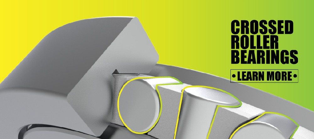
For applications carrying substantial radial, axial, and moment loads in one compact rotary axis, a crossed roller bearing may be the more suitable choice. For high-speed shafts requiring low friction, controllable preload, and precise guidance, angular contact ball bearings are often the preferred solution.
Work With a Precision Bearing Manufacturer
The best bearing solution begins with accurate application information. A detailed technical discussion can prevent costly redesign, unexpected vibration, overheating, premature wear, and field failures.
Henan Yuwei Industrial Technology Co., Ltd. provides precision crossed roller bearings, high-rigidity crossed roller bearings, thin-section crossed roller bearings, double-row crossed roller bearings, high-precision angular contact ball bearings, high-speed angular contact ball bearings, and long-life angular contact ball bearing solutions.
Our products are used in robotics, CNC machine tools, reducers, rotary tables, direct-drive motors, radar equipment, medical devices, precision measurement equipment, and industrial automation systems. Through long-term technical cooperation with universities and research institutions, we support specialized bearing development for demanding motion applications.
Send us your drawing, bearing model number, installation dimensions, radial load, axial load, moment load, speed, accuracy requirement, lubrication condition, and annual quantity. Our engineering team can evaluate your operating requirements and recommend a suitable bearing arrangement for your application.
Frequently Asked Questions
What is a back-to-back angular contact ball bearing arrangement?
A back-to-back arrangement uses two angular contact ball bearings installed with their wide ends facing outward. The contact lines diverge away from each other, creating a wide support span that improves stiffness and resistance to tilting moments.
Why is a DB arrangement used in machine tool spindles?
Machine tool spindles need high rotational accuracy, strong axial support, and good resistance to cutting-force-induced shaft deflection. A DB arrangement provides axial load capacity in both directions and helps maintain stable spindle positioning under changing loads.
Is back-to-back better than face-to-face for all applications?
No. A DB arrangement generally provides higher moment stiffness, while a face-to-face arrangement may tolerate slight misalignment better. The correct choice depends on the machine structure, load direction, required stiffness, and installation accuracy.
Can back-to-back bearings support axial loads in both directions?
Yes. A properly mounted DB pair can support axial loads from either direction. This makes it suitable for reversing shafts, servo systems, robotic axes, and other applications with changing thrust loads.
How does preload affect a DB bearing pair?
Preload removes internal clearance and can increase rigidity, positioning accuracy, and vibration resistance. However, excessive preload can increase heat, friction, torque, and wear. The preload level should match the application’s speed, load, temperature, and accuracy requirements.
Can I install two standard bearings as a back-to-back pair?
It is possible in some applications, but precision systems should normally use matched bearings designed for paired mounting. Matched pairs help ensure proper preload, dimensional consistency, and balanced load distribution.
What causes excessive heat in back-to-back angular contact ball bearings?
Common causes include excessive preload, unsuitable lubrication, high speed, poor heat dissipation, misalignment, incorrect mounting force, contamination, and excessive interference fits. Temperature rise should be investigated early to avoid raceway damage or lubricant degradation.
When should I choose a crossed roller bearing instead of a DB angular contact bearing pair?
Choose a crossed roller bearing when the application requires very high rigidity and must carry radial load, axial loads in both directions, and overturning moment in one compact bearing unit. It is often preferred for robot joints, rotary tables, reducers, and precision platforms.
References
1. [AMIGO – Benefits of Angular Contact Ball Bearing Back-to-Back Design]
2. [SKF – Angular Contact Ball Bearings]
3. [SKF – Bearing Arrangements and Paired Angular Contact Ball Bearings]
4. [ISO – ISO 281: Rolling Bearings, Dynamic Load Ratings and Rating Life]
5. [Schaeffler – Angular Contact Ball Bearings]
6. [Schaeffler – Rolling Bearing Arrangement Design]
7. [Henan Yuwei – Crossed Roller Bearings and Angular Contact Ball Bearings for Precision Motion Systems]
8. [Henan Yuwei – Super Precision Bearing Manufacturer]
Hot Tags: Angular Contact Ball Bearings, Back To Back Angular Contact Bearings, DB Arrangement Bearings, Precision Angular Contact Ball Bearings, High Speed Angular Contact Bearings, Spindle Angular Contact Bearings, Angular Contact Bearing Manufacturer, Matched Angular Contact Bearing Pairs, Industrial Robot Bearings, CNC Machine Tool Bearings