Content Menu
● Why Bearing Selection Matters in Semiconductor Equipment
● Angular Contact Ball Bearing Overview
>> How Angular Contact Ball Bearings Carry Load
>> Strengths of Angular Contact Ball Bearings
>> Limitations of Angular Contact Ball Bearings
● Cross Roller Bearing Overview
>> Why Cross Roller Bearings Provide High Rigidity
>> Key Benefits of Cross Roller Bearings
>> Cross Roller Bearing Trade-Offs
● Angular Contact Ball Bearing vs Cross Roller Bearing: Core Comparison
● Application-by-Application Selection Guide
>> Wafer Handling Robots and Transfer Arms
>> Precision Rotary Stages and Wafer Indexing Tables
>> High-Speed Spindles and Rotating Process Modules
>> Vacuum-Compatible and Cleanroom-Related Mechanisms
● Expert Selection Framework for Engineers
>> Five Questions Before Requesting a Bearing Proposal
● Installation Quality Can Decide Final Performance
● Selecting Yuwei Bearings for Semiconductor Motion Systems
>> 1. Which bearing is better for semiconductor wafer-handling robots?
>> 2. Can angular contact ball bearings handle axial loads in both directions?
>> 3. Are cross roller bearings suitable for high-speed semiconductor equipment?
>> 4. Why are cross roller bearings more rigid than angular contact ball bearings?
>> 5. What information should be provided when selecting a precision bearing?
>> 6. Can one cross roller bearing replace two angular contact ball bearings?
>> 7. What causes high torque in a cross roller bearing?
For semiconductor manufacturing equipment, the choice between an angular contact ball bearing and a cross roller bearing affects far more than simple rotational support. It can influence wafer-positioning stability, repeatability, vibration control, tool uptime, contamination-management strategy, and the usable life of a precision motion system.
In practical equipment design, cross roller bearings are often the stronger choice for low-speed, high-rigidity, multi-directional-load applications such as wafer-transfer robots, inspection stages, rotary indexing mechanisms, and compact precision platforms. Angular contact ball bearings are often preferred where higher rotational speed, low friction, flexible bearing arrangements, and economical spindle support are the primary objectives. The best bearing is not determined by product category alone; it depends on the load path, speed profile, required runout, mounting space, environmental conditions, and maintenance plan.
Henan Yuwei Industrial Technology Co., Ltd. develops precision cross cylindrical roller bearings, high-rigidity cross roller bearings, thin-section cross roller bearings, double-row cross roller bearings, and high-precision angular contact ball bearings for advanced motion systems. Through technical cooperation with universities and research institutions, Yuwei supports bearing solutions for robotics, precision measurement, radar, machine tools, rotary tables, harmonic reducers, planetary reducers, medical equipment, and automated handling equipment.

Why Bearing Selection Matters in Semiconductor Equipment
Semiconductor tools operate under much tighter mechanical and environmental limits than ordinary industrial machinery. A small angular error, a change in preload, an increase in torque variation, or microscopic particulate contamination may affect repeatability, alignment, process stability, or equipment availability.
Many semiconductor systems combine several difficult operating requirements:
– High positioning accuracy for wafer alignment, inspection, exposure, and handling
– High rigidity to resist changing radial, axial, and overturning-moment loads
– Compact installation space inside robotic arms, transfer modules, stages, and rotary units
– Low vibration and stable torque during repeated motion cycles
– Clean manufacturing compatibility for controlled environments and vacuum-related systems
– Long service life under high-frequency start-stop operation
– Reliable preload retention throughout the equipment life cycle
In cleanroom and vacuum-related production environments, contamination control is a core engineering concern. Semiconductor cleanrooms are designed to minimize airborne particles, contaminants, and pollutants, while vacuum equipment requires stable pressure and cleanliness management. Bearing selection therefore cannot be isolated from the wider mechanical design, lubrication approach, sealing method, cleaning process, packaging standard, and operating environment.
A precision bearing should be evaluated as part of the complete motion module—not as an individual catalog component.
Angular Contact Ball Bearing Overview
An angular contact ball bearing uses balls as rolling elements. Its raceways are designed so that the ball-to-raceway contact occurs at a defined contact angle. This geometry allows the bearing to carry radial load and axial load in one direction simultaneously.
Because the balls make relatively small contact areas with the raceways, angular contact ball bearings typically offer lower friction and better high-speed capability than roller-based bearing designs.
How Angular Contact Ball Bearings Carry Load
A single-row angular contact ball bearing normally supports:
– Radial loads
– Axial loads in one direction
– Combined radial and axial loads
– Controlled preload for improved rigidity and rotational accuracy
For bidirectional axial loads or higher moment resistance, designers commonly use matched bearing arrangements:
– Back-to-back arrangement: Provides a wider effective support span and strong resistance to overturning moments
– Face-to-face arrangement: Offers better tolerance for minor shaft or housing misalignment
– Tandem arrangement: Increases axial load capacity in one direction
Double-row angular contact ball bearings integrate the functional behavior of two single-row bearings in a shared ring structure.
Strengths of Angular Contact Ball Bearings
Angular contact ball bearings can be highly effective in semiconductor equipment when speed, smoothness, and configuration flexibility matter most.
Their key advantages include:
– High rotational speed capability
– Lower friction torque than many roller-bearing alternatives
– Good axial load performance when installed as matched pairs
– Flexible preload selection
– Multiple arrangement options for spindle and rotary-axis design
– Widely available precision grades
– Potentially lower system cost in suitable applications
High-speed angular contact ball bearings are especially relevant for precision spindles, compact rotary units, high-speed inspection mechanisms, and equipment modules where a cross roller bearing may introduce more starting torque or heat at elevated speed.
Limitations of Angular Contact Ball Bearings
The fundamental trade-off is rigidity. Balls contact the raceways at localized contact points, while cylindrical rollers provide longer line contact. Under high external moments, changing direction loads, and demanding positioning tasks, angular contact ball bearings may require paired sets, larger bearing spacing, optimized housings, or more complex mounting designs to reach the required stability.
Angular contact ball bearing performance may be less favorable when the application requires:
– A single compact bearing to carry radial, axial, and moment loads
– Very high tilting stiffness
– Minimal elastic deformation under changing loads
– High resistance to overturning moments
– Simplified compact mounting in a narrow envelope
Cross Roller Bearing Overview
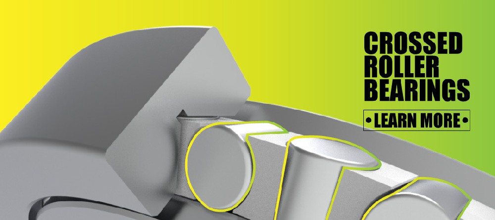
A cross roller bearing uses cylindrical rollers arranged alternately at approximately 90 degrees between inner and outer rings. This crossed arrangement enables one bearing to carry radial load, axial load in both directions, and overturning moment load simultaneously.
The roller orientation is the defining feature. Adjacent rollers are positioned perpendicular to one another, allowing the bearing to manage complex loads from multiple directions within a compact structure.
Why Cross Roller Bearings Provide High Rigidity
The line contact between cylindrical rollers and raceways distributes load across a greater contact area than ball-to-raceway point contact. This geometry helps reduce elastic deformation and improves structural stiffness under combined loading.
For semiconductor manufacturing equipment, this can be critical. A rotating platform may experience vertical payload load, side force from cabling, acceleration-induced radial load, and an overturning moment created by an offset wafer carrier. A cross roller bearing can support these combined forces through one compact bearing unit.
Cross roller bearings are widely used in precision machinery because they can manage radial, axial, and moment loads while maintaining high stiffness and rotational accuracy.
Key Benefits of Cross Roller Bearings
A high-precision cross roller bearing can provide the following benefits:
– High radial, axial, and moment-load capacity
– High rigidity in a compact envelope
– Strong resistance to tilting and deflection
– High rotational accuracy
– Simplified mechanical architecture
– Potential replacement of two-bearing support structures
– Stable motion for start-stop indexing applications
– Suitable support for compact robotic joints and rotary tables
IKO reports that one compact crossed roller bearing design can provide rigidity up to four times greater than double-row angular-contact-ball-bearing designs in certain configurations. This figure should not be treated as a universal design rule, because bearing size, preload, installation stiffness, loading direction, and operating conditions can materially change the result. However, it highlights why crossed roller bearings are frequently evaluated first for compact high-rigidity motion systems.
Cross Roller Bearing Trade-Offs
Cross roller bearings are not automatically the best choice for every semiconductor axis. Their major trade-offs include:
– Higher starting torque than many ball-bearing systems
– More demanding mounting-surface requirements
– Greater sensitivity to assembly accuracy
– Potential heat generation at high speeds
– Higher product and machining cost for precision configurations
– Need for careful preload and clearance control
For sustained high-speed rotation, a precision angular contact ball bearing arrangement may deliver lower friction and lower temperature rise. For slow-to-medium-speed rotation with stringent stiffness and positioning requirements, a cross roller bearing is often more suitable.
Angular Contact Ball Bearing vs Cross Roller Bearing: Core Comparison
| Comparison Factor | Angular Contact Ball Bearing | Cross Roller Bearing |
|---|---|---|
| Rolling element | Precision balls | Cylindrical rollers arranged at 90 degrees |
| Contact geometry | Point contact | Line contact |
| Radial load capacity | Good | High |
| Axial load capacity | One direction per single-row bearing; bidirectional when paired | High axial capacity in both directions |
| Moment-load capacity | Requires paired bearings and sufficient spacing | High moment capacity in one compact bearing |
| Rigidity | Moderate to high with preload and matched pairs | Very high, especially under combined loads |
| Rotational speed | Usually better for high-speed operation | Generally more suitable for low-to-medium-speed precision rotation |
| Friction and torque | Typically lower | Typically higher, especially at start-up |
| Installation design | Flexible but may require multiple bearings | Compact single-bearing support possible |
| Alignment tolerance | Depends on arrangement; face-to-face pairs can accommodate limited misalignment | Requires high mounting accuracy and flatness |
| Typical semiconductor roles | High-speed spindles, compact rotary modules, selected inspection axes | Wafer robots, precision rotary stages, indexing platforms, transfer mechanisms |
| Cost profile | Often more economical for conventional designs | Often higher due to precision machining and integrated capability |
The most important distinction is simple: angular contact ball bearings optimize speed and configuration flexibility, while cross roller bearings optimize compact rigidity and multi-directional load support.
Application-by-Application Selection Guide
The phrase “semiconductor manufacturing equipment” covers many different motion systems. The correct bearing depends on the duty cycle and function of each axis.
Wafer Handling Robots and Transfer Arms
Wafer-handling robots must move quickly while maintaining repeatable positioning. Their joints may experience bending moments from extended arms, payload changes, acceleration, deceleration, and cable drag.
A cross roller bearing is often the preferred option for compact robot joints because it can support radial loads, axial loads, and moment loads in a single bearing. This can reduce structural complexity and improve arm rigidity.
Recommended focus:
– High moment rigidity
– Controlled rotational accuracy
– Compact cross section
– Stable preload
– Low vibration during repeated start-stop cycles
– Clean lubrication and protective sealing strategy
Cross roller bearings are used in semiconductor fabrication equipment, including wafer-handling robots and lithography-related motion systems, where precise alignment and positioning are required.

Precision Rotary Stages and Wafer Indexing Tables
Rotary stages used for wafer orientation, inspection, metrology, or process positioning require high repeatability. Even a small angular deviation can affect measurement consistency or process alignment.
A high-rigidity cross roller bearing is generally a strong choice where the stage experiences an offset payload or external moment load. Its ability to resist tilt can help preserve the flatness and angular stability of the rotating platform.
A matched angular contact ball bearing pair may still be suitable when:
– The stage rotates at higher speed
– Moment load is limited
– There is enough axial space for a separated bearing arrangement
– Lower torque is more important than maximum rigidity
High-Speed Spindles and Rotating Process Modules
For high-speed spindle assemblies, angular contact ball bearings are commonly considered because low friction and high-speed capability are essential. Matched pairs can provide axial control and preload while maintaining smooth rotation.
A high-speed angular contact ball bearing may be the better option when the design priorities are:
– High RPM capability
– Low running torque
– Thermal stability
– Controlled preload
– High-speed balancing compatibility
– Reduced frictional heat
The final choice must consider spindle diameter, lubrication method, speed factor, preload, heat path, housing material, and cooling strategy.

Vacuum-Compatible and Cleanroom-Related Mechanisms
Bearings in vacuum-related semiconductor equipment require special engineering attention. A mechanically appropriate bearing may still fail the system requirement if its lubricant, cage material, seals, cleaning process, or packaging method is unsuitable for the environment.
Before selecting either bearing type, verify:
1. Lubrication compatibility with the operating environment
2. Particle-generation risk during running and start-stop motion
3. Material selection, including rings, rolling elements, cages, and fasteners
4. Cleaning process before assembly
5. Packaging standard for cleanroom delivery
6. Outgassing and vacuum requirements, where applicable
7. Life-test conditions that match real equipment duty cycles
Precision cleaning is especially important in semiconductor and advanced manufacturing systems because particles, residues, and contamination within vacuum equipment can affect process performance and equipment uptime.
Expert Selection Framework for Engineers
In bearing projects involving robotic joints, rotary tables, semiconductor automation, or precision positioning equipment, experienced engineers do not begin with the question, “Which bearing is better?”
They begin with: “Which failure mode is least acceptable?”
For example:
– If unacceptable failure means stage tilt under payload, prioritize cross roller rigidity.
– If unacceptable failure means excess heat at high RPM, prioritize angular contact ball bearing speed performance.
– If unacceptable failure means difficult installation within a narrow structure, consider a thin-section cross roller bearing.
– If unacceptable failure means insufficient bidirectional axial support, compare cross roller bearings against paired or double-row angular contact designs.
– If unacceptable failure means torque variation during low-speed indexing, evaluate preload, lubrication, surface finish, and runout—not only bearing type.
Five Questions Before Requesting a Bearing Proposal
Provide these parameters to the bearing manufacturer:
1. What are the radial, axial, and moment loads?
Include peak loads, continuous loads, shock loads, and load direction.
2. What is the speed profile?
Specify continuous RPM, maximum RPM, acceleration, deceleration, and start-stop frequency.
3. What accuracy is required?
Define radial runout, axial runout, tilt error, rotational accuracy, and repeatability targets.
4. What is the installation envelope?
Include inner diameter, outer diameter, section height, bolt pattern, housing arrangement, and available bearing spacing.
5. What is the operating environment?
Confirm cleanroom class, vacuum requirement, temperature, corrosion exposure, lubrication limits, and maintenance accessibility.
This information allows the bearing supplier to recommend a bearing series, precision grade, preload or clearance condition, lubrication option, mounting tolerance, and inspection method with greater confidence.
Installation Quality Can Decide Final Performance
A premium bearing cannot compensate for poor mounting surfaces. In precision semiconductor equipment, actual system accuracy depends on both bearing quality and integration quality.
For cross roller bearings, special attention should be given to:
– Mounting-face flatness
– Housing and shaft roundness
– Perpendicularity between locating surfaces
– Tightening sequence and bolt torque consistency
– Avoidance of uneven clamping force
– Correct positioning of retaining rings
– Clean assembly conditions
For angular contact ball bearings, pay close attention to:
– Correct bearing orientation
– Matched-set identification
– Preload direction and preload level
– Spacer precision
– Shaft and housing fits
– Thermal expansion behavior
– Axial clamping force
An assembly error can create excessive preload, local stress, increased torque, heat generation, vibration, and shortened bearing life. Therefore, bearing selection should include an installation review, not just a dimensional drawing review.
Selecting Yuwei Bearings for Semiconductor Motion Systems
Henan Yuwei Industrial Technology Co., Ltd. supports customers requiring precision-bearing solutions for demanding motion systems. Its product range includes:
– Precision cross cylindrical roller bearings
– High-rigidity cross roller bearings
– Thin-section cross roller bearings
– Double-row cross roller bearings
– High-precision angular contact ball bearings
– High-speed angular contact ball bearings
– Long-life angular contact ball bearings
For a compact wafer-transfer joint, a thin-section or high-rigidity cross roller bearing may help maximize stiffness without consuming excessive installation space. For a high-speed rotating axis, a high-precision angular contact ball bearing arrangement may offer a better balance of speed, torque, and thermal behavior.
The most effective approach is to share the real application data early. A bearing supplier can then evaluate the load spectrum, structural space, speed, precision target, environment, and expected service life before recommending a specific bearing configuration.
Contact Yuwei Bearing with your drawing, load data, rotation speed, target accuracy, and operating environment to receive a tailored bearing selection proposal for your semiconductor manufacturing equipment.
Frequently Asked Questions
1. Which bearing is better for semiconductor wafer-handling robots?
A cross roller bearing is often better for compact wafer-handling robot joints because it can withstand radial loads, axial loads, and overturning moments simultaneously. Its high rigidity can help maintain arm stability and repeatable wafer positioning. The final selection should still consider arm speed, payload, acceleration, installation space, and clean-environment requirements.
2. Can angular contact ball bearings handle axial loads in both directions?
A single-row angular contact ball bearing supports axial load mainly in one direction. To support axial load in both directions, engineers typically use matched pairs in back-to-back or face-to-face arrangements, or use a double-row angular contact ball bearing.
3. Are cross roller bearings suitable for high-speed semiconductor equipment?
They can be suitable for certain moderate-speed precision axes, but they are not always the best option for sustained high-speed rotation. Their higher contact area and preload requirements can increase torque and heat. For high-speed spindles and fast rotary modules, high-precision angular contact ball bearings are often more appropriate.
4. Why are cross roller bearings more rigid than angular contact ball bearings?
Cross roller bearings use cylindrical rollers with line contact against the raceways. This larger contact area helps distribute load and reduce elastic deformation. Their crossed roller arrangement also supports radial, axial, and moment loads in one compact unit. Angular contact ball bearings use balls with more localized contact points, so they may need matched pairs and a wider support span to achieve comparable moment stiffness.
5. What information should be provided when selecting a precision bearing?
Provide load data, rotation speed, duty cycle, shaft and housing dimensions, required radial and axial runout, allowable tilt, installation space, temperature range, lubrication requirements, cleanroom or vacuum conditions, and expected operating life. The more complete the application data, the more accurate the bearing recommendation will be.
6. Can one cross roller bearing replace two angular contact ball bearings?
In many compact rotary or robotic-joint designs, one cross roller bearing can perform the radial, axial, and moment-support functions that would otherwise require two angular contact ball bearings. However, replacement must be verified through load calculation, speed analysis, installation design, torque evaluation, and life prediction.
7. What causes high torque in a cross roller bearing?
Common causes include excessive preload, poor mounting-surface flatness, uneven bolt tightening, contamination, improper lubrication, incorrect fit, misalignment, or excessive external load. Proper bearing selection and controlled installation are essential for stable torque performance.
References
1. [NSK — Angular Contact Ball Bearings]
2. [IKO — Crossed Roller Bearing Rigidity Technology Update]
3. [Bearings ‘R Us — Crossed Roller Bearings Overview]
4. [Pfeiffer Vacuum — Semiconductor Manufacturing Vacuum Solutions]
5. [VEM — Precision Cleaning for Semiconductor and Advanced Manufacturing]
6. [Lily Bearing — Advantages of Cross Roller Bearings]
7. [PRSBearings — Crossed Roller Bearings vs. Angular Contact Ball Bearings]
Hot Tags: Angular Contact Ball Bearing, Cross Roller Bearing, Semiconductor Equipment Bearings, Precision Bearings, Crossed Roller Bearing, High Precision Angular Contact Bearing, Wafer Handling Robot Bearings, Semiconductor Robot Bearings, Precision Rotary Table Bearings, Cleanroom Bearing Solutions