Content Menu
● What Is the Difference Between Angular Contact Ball Bearings and Cross Roller Bearings?
● Angular Contact Ball Bearing vs Cross Roller Bearing: Quick Comparison
● Why Angular Contact Ball Bearings Perform Better at High Speed
>> Key Advantages for High-Speed Equipment
>> Common Angular Contact Arrangements
● Why Cross Roller Bearings Excel in High-Rigidity Automation
>> Main Advantages of Cross Roller Bearings
● The Critical Factor: Speed Is More Than RPM
>> Evaluate These Operating Conditions
● Load Capacity and Rigidity: Where Cross Roller Bearings Win
>> Typical Cross Roller Bearing Applications
● Thermal Management and Preload Control
>> Practical Engineering Guidance
● A Practical Selection Workflow for Automation Designers
>> Step 1: Define the Duty Cycle
>> Step 2: Calculate All External Loads
>> Step 3: Set Precision Targets
>> Step 4: Review Installation Space
>> Step 5: Validate Lubrication and Heat Dissipation
>> Step 6: Test the Real Assembly
● Which Bearing Should You Choose?
● Partner With Yuwei for Precision Bearing Selection
>> 1. Are angular contact ball bearings suitable for robot joints?
>> 2. Can a cross roller bearing run at high speed?
>> 3. Which bearing has higher rigidity: angular contact or cross roller?
>> 4. Why are angular contact ball bearings often installed in pairs?
>> 5. What causes excessive bearing temperature in high-speed automation equipment?
>> 6. Is a cross roller bearing better for a harmonic reducer?
>> 7. How should bearing life be calculated?
Selecting between an angular contact ball bearing and a cross roller bearing can directly affect the speed, rigidity, positioning accuracy, service life, and total cost of an automation system. For high-speed automation equipment, the right choice is rarely based on load capacity alone—it depends on the complete operating profile, including rpm, moment load, acceleration, mounting accuracy, lubrication, thermal behavior, and required repeatability.
For robot joints, hollow rotary platforms, machine-tool spindles, radar positioning systems, precision turntables, and compact reducers, angular contact ball bearings are often the stronger option for sustained high-speed rotation. Cross roller bearings are typically preferred where a single compact bearing must carry radial, axial, and overturning moment loads with very high rigidity and positioning stability.
Henan Yuwei Industrial Technology Co., Ltd. develops precision cross roller bearings and high-precision angular contact ball bearings for demanding automation applications. Based on practical bearing-selection experience across robotics, precision machinery, radar equipment, medical devices, and rotary transmission systems, this guide explains how to choose the right bearing configuration for your equipment.

What Is the Difference Between Angular Contact Ball Bearings and Cross Roller Bearings?
An angular contact ball bearing uses balls running between inner and outer raceways at a defined contact angle. This geometry enables the bearing to support combined radial and axial loads. It is widely used in high-speed spindles, servo motors, pumps, compressors, precision machine tools, and robotic drive assemblies.
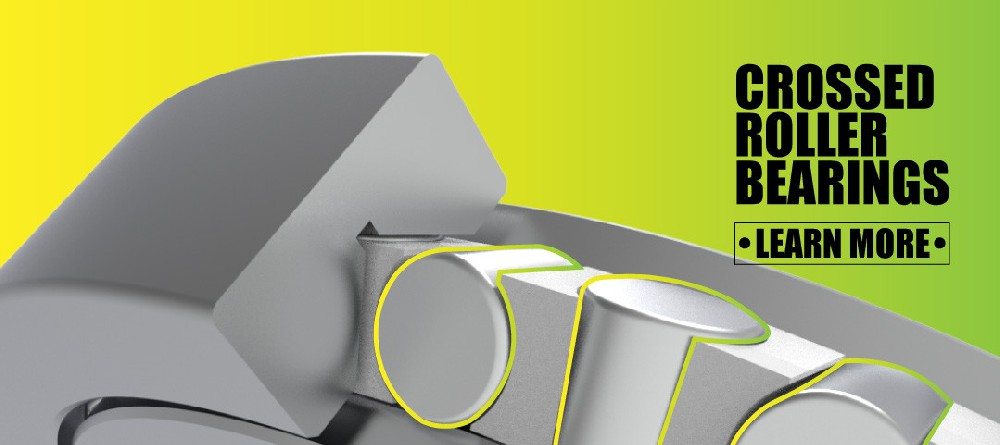
A cross roller bearing uses cylindrical rollers arranged alternately at 90 degrees. One roller is oriented to carry load in one direction, while the adjacent roller is positioned perpendicularly. This crossed arrangement allows one bearing to support radial load, axial load in both directions, and overturning moment load.
The core difference is simple:
– Angular contact ball bearings prioritize speed, low friction, and smooth rotation.
– Cross roller bearings prioritize rigidity, moment capacity, compact integration, and precision under combined loads.
A roller bearing generally provides higher rigidity than a ball bearing of the same size because the roller-to-raceway contact is closer to line contact, while a ball bearing operates with point contact.
Angular Contact Ball Bearing vs Cross Roller Bearing: Quick Comparison
| Selection Factor | Angular Contact Ball Bearing | Cross Roller Bearing |
|---|---|---|
| Rolling element | Precision balls | Cylindrical rollers arranged at 90 degrees |
| Typical strength | High rotational speed | High rigidity and moment capacity |
| Friction level | Usually lower | Usually higher than ball-bearing designs |
| Speed capability | Excellent for high-speed operation | Moderate; application-specific limits apply |
| Axial load | Strong in one direction per single bearing | Supports axial loads in both directions |
| Radial load | Good | Good to high |
| Overturning moment | Requires paired or grouped arrangement | Excellent within one bearing |
| Rotational accuracy | Very high with suitable preload and precision class | Very high, especially for rotary positioning |
| Installation space | Often requires paired bearings for bidirectional load | Compact single-bearing solution |
| Typical applications | Spindles, motor shafts, high-speed rotary units | Robot joints, turntables, reducers, radar mounts |
| Main design risk | Heat and preload increase at high rpm | Friction, heat, and speed limitations under fast duty cycles |
Why Angular Contact Ball Bearings Perform Better at High Speed
For genuinely high-speed automation equipment, angular contact ball bearings are usually the first design direction. Their ball rolling elements create lower internal friction than cylindrical roller designs, especially when the bearing is correctly preloaded, lubricated, and mounted.
At higher rotational speeds, frictional heat becomes a major engineering concern. Excessive heat can change internal clearance, reduce lubricant film quality, increase preload, and accelerate wear. SKF notes that preload changes with rotational speed and can increase significantly at very high speeds.
Key Advantages for High-Speed Equipment
– Lower rolling friction than cross roller bearings
– Better suitability for continuous high-rpm operation
– High rotational smoothness
– Strong response to radial and axial combined loads
– Available in matched pairs for controlled preload and bidirectional axial support
– Well suited to oil-air lubrication, oil mist lubrication, and high-speed grease systems
– Easier to configure for spindle-like arrangements
A single-row angular contact ball bearing carries axial load primarily in one direction. For bidirectional axial loads, designers commonly use a duplex arrangement, such as back-to-back (DB), face-to-face (DF), or tandem (DT).
Common Angular Contact Arrangements
| Arrangement | Main Benefit | Typical Use |
|---|---|---|
| Back-to-back (DB) | High moment stiffness and wider effective support span | Machine-tool spindles, servo shafts |
| Face-to-face (DF) | Better tolerance for shaft and housing misalignment | General precision rotary assemblies |
| Tandem (DT) | Higher axial load capacity in one direction | High-thrust drive systems |
| Multi-row configuration | Higher stiffness and load capacity | High-performance spindle systems |
For example, a high-speed SCARA robot axis may need rapid acceleration, repeated short cycles, low torque loss, and smooth servo control. A preloaded angular contact ball bearing pair can provide the needed speed capability while controlling axial displacement. If the same axis also has a large offset payload that creates a severe overturning moment, a cross roller bearing or hybrid bearing arrangement may be more appropriate.

Why Cross Roller Bearings Excel in High-Rigidity Automation
Cross roller bearings are designed for applications where the bearing itself must function as a compact structural support. Their alternating roller arrangement enables one bearing to carry loads from multiple directions while maintaining high rigidity.
This makes a precision cross roller bearing highly valuable in robotics, precision rotary tables, harmonic reducers, medical imaging systems, radar antennas, and inspection equipment.
Main Advantages of Cross Roller Bearings
– Supports radial, axial, and moment loads in one compact unit
– High tilting rigidity for cantilevered loads
– Excellent for precision rotary positioning
– Reduced need for multiple bearing sets
– Compact axial design
– Good rotational accuracy when mounting surfaces are precisely machined
– Suitable for hollow rotary structures and compact robot joints
Cross roller bearings are especially effective when the load acts away from the bearing centerline. This is common in robot arms, end-effectors, radar platforms, camera systems, and industrial turntables. Even if the direct radial and axial loads are moderate, an offset load can generate a substantial overturning moment.
A high-rigidity cross roller bearing can reduce angular deflection, helping protect gear meshes, encoders, harmonic reducers, and precision sensors from alignment errors.

The Critical Factor: Speed Is More Than RPM
Many engineers compare bearings by looking only at rpm. This can lead to poor bearing selection. The more useful question is:
What combination of speed, load, moment, acceleration, temperature, and duty cycle will the bearing actually experience?
A bearing operating at 3,000 rpm under light, stable load may be easier to manage than a bearing operating at 1,000 rpm with rapid reversals, heavy moment loading, poor lubrication, and repeated emergency stops.
Evaluate These Operating Conditions
1. Maximum and continuous rotational speed
2. Radial load, axial load, and overturning moment
3. Load direction and whether it changes during operation
4. Acceleration and deceleration frequency
5. Required positioning accuracy and repeatability
6. Allowable temperature rise
7. Lubrication method and relubrication access
8. Space restrictions and hollow-shaft requirements
9. Mounting surface flatness and shaft/housing tolerances
10. Required operating life and maintenance interval
Bearing life should be evaluated with actual equivalent load, not only nominal load. ISO 281 provides methods for calculating dynamic load ratings and rating life, including factors related to lubrication, contamination, and reliability.
The basic dynamic load rating is associated with a calculated life of 1,000,000 revolutions at 90% reliability under defined conditions.
Load Capacity and Rigidity: Where Cross Roller Bearings Win
For applications with high moment loads, cross roller bearings often offer a more direct and space-efficient solution. A single cross roller bearing can support radial force, bidirectional axial force, and overturning moment without requiring the wider bearing spacing normally needed in angular contact ball bearing pairs.
This advantage matters in compact automation systems. For example, a collaborative robot wrist may have limited installation space but must resist the bending moment created by a tool, cable package, gripper, and variable payload.
Typical Cross Roller Bearing Applications
– Harmonic reducer output support
– Planetary reducer output stages
– Robot shoulder, elbow, wrist, and waist joints
– AGV steering modules
– Medical robot joints
– CNC rotary tables
– Hollow rotary platforms
– Radar and antenna positioning systems
– Precision measuring instruments
– Semiconductor and inspection equipment
However, high rigidity does not automatically mean cross roller bearings are the best choice for every precision system. If the system runs at sustained high speed, thermal control and friction torque may become more important than maximum moment stiffness.
Thermal Management and Preload Control
Preload is one of the most important variables in both bearing types. Proper preload can improve stiffness, axial positioning, and vibration resistance. Excessive preload raises friction torque and heat generation, especially at high speed.
For angular contact ball bearings, preload must be matched to the speed range, lubrication method, fit conditions, and thermal expansion behavior of the shaft and housing. A preload that works well during slow inspection may become excessive during continuous high-speed production.
For cross roller bearings, preload or internal clearance selection must also consider mounting accuracy. Uneven mounting surfaces, excessive tightening, or ring distortion can cause localized roller loading and elevated running torque.
Practical Engineering Guidance
– Use light or medium preload when speed is the dominant requirement.
– Use higher preload only when the gain in rigidity justifies the added heat and torque.
– Control shaft and housing geometry before increasing preload.
– Verify running torque after installation.
– Confirm temperature stabilization during the real operating cycle.
– Select lubrication according to speed factor, load, environment, and maintenance access.
– Do not evaluate bearing performance from static load data alone.
A Practical Selection Workflow for Automation Designers
The following process can reduce redesign risk when selecting an angular contact ball bearing or cross roller bearing.
Step 1: Define the Duty Cycle
Record continuous speed, maximum speed, acceleration, cycle frequency, stopping behavior, and expected annual operating hours. A robot joint that reverses direction every second has a very different duty profile from a continuously rotating spindle.
Step 2: Calculate All External Loads
Include radial load, axial load, and overturning moment. Do not ignore load generated by the center-of-gravity offset of tooling, cables, reducers, or workpieces.
Step 3: Set Precision Targets
Define allowable radial runout, axial displacement, tilt angle, repeatability, and vibration limits. These values determine whether rigidity or speed capability should take priority.
Step 4: Review Installation Space
If the equipment has a short axial length and must support loads in multiple directions, a cross roller bearing may simplify the design. If there is room for a duplex angular contact arrangement, the system may achieve better high-speed performance.
Step 5: Validate Lubrication and Heat Dissipation
Determine whether grease, oil-air, oil mist, or circulating oil is feasible. High-speed equipment may require a lubrication method that actively limits heat generation and maintains a stable film.
Step 6: Test the Real Assembly
Test the complete shaft, housing, fasteners, seals, motor, reducer, and load. The bearing cannot be evaluated in isolation because housing distortion, assembly tolerance, and preload variation can change actual performance.
Which Bearing Should You Choose?
Choose an angular contact ball bearing when your automation equipment requires:
– Sustained high rotational speed
– Low friction torque
– High-speed servo response
– Smooth spindle-like rotation
– Accurate axial positioning with matched bearing pairs
– Controlled thermal performance
– High-speed motor, spindle, or rotary shaft support
Choose a cross roller bearing when your equipment requires:
– High rigidity in a compact structure
– Strong resistance to overturning moments
– Radial and axial load capacity in both directions
– High rotary positioning accuracy
– A single bearing to replace a more complex bearing arrangement
– Support for robot joints, turntables, reducers, or radar mechanisms
– Low angular deflection under offset loads
For some advanced systems, the best solution is not an either-or choice. A robot reducer output may use a cross roller bearing for moment support, while the motor or high-speed input stage uses high-precision angular contact ball bearings. This division allows each bearing type to perform where it is strongest.
Partner With Yuwei for Precision Bearing Selection
Yuwei Bearing supports automation equipment manufacturers with precision cross roller bearings, high-rigidity cross roller bearings, thin-section cross roller bearings, double-row cross roller bearings, high-precision angular contact ball bearings, high-speed angular contact ball bearings, and long-life angular contact ball bearing solutions.
Our engineering team can support bearing selection based on your actual application conditions, including speed, load spectrum, moment load, installation space, rotational accuracy, lubrication method, and expected operating life. For robot manufacturers, reducer manufacturers, machine-tool builders, medical equipment producers, and precision automation integrators, early bearing selection can prevent expensive redesigns later in development.
Contact Yuwei Bearing with your drawings, load data, speed range, and application requirements to receive a practical bearing recommendation for your high-speed automation equipment.
Frequently Asked Questions
1. Are angular contact ball bearings suitable for robot joints?
Yes. They are suitable for robot joints that require high speed, low friction, and controlled axial positioning. For joints with high overturning moment, cross roller bearings are often more suitable.
2. Can a cross roller bearing run at high speed?
It can run at moderate to high speed depending on size, preload, lubrication, load, and mounting conditions. However, for continuous high-speed rotation, angular contact ball bearings are usually the more efficient choice.
3. Which bearing has higher rigidity: angular contact or cross roller?
A cross roller bearing generally provides higher rigidity in a compact single-bearing design, particularly against overturning moment loads. Roller bearings normally provide higher rigidity than ball bearings of the same size.
4. Why are angular contact ball bearings often installed in pairs?
A single angular contact ball bearing primarily supports axial load in one direction. Pairing bearings allows bidirectional axial support and can increase system stiffness and moment capacity.
5. What causes excessive bearing temperature in high-speed automation equipment?
Common causes include excessive preload, unsuitable lubrication, incorrect bearing fits, high friction torque, poor heat dissipation, contamination, and operating beyond the recommended speed range.
6. Is a cross roller bearing better for a harmonic reducer?
In many harmonic reducer output applications, yes. Cross roller bearings are well suited because they support combined radial, axial, and moment loads while maintaining compact structure and high rotational rigidity.
7. How should bearing life be calculated?
Bearing life should be calculated using the bearing’s dynamic load rating, equivalent dynamic load, rotational speed, lubrication condition, contamination level, and required reliability. ISO 281 provides the general framework for this type of calculation.
References
– [SKF: Preload, Clearance and Stiffness for Angular Contact Ball Bearings]
– [ISO 281:2007 — Rolling Bearings: Dynamic Load Ratings and Rating Life]
– [SKF: Basic Dynamic Load Rating, C]
– [NTN: Precision Rolling Bearings Technical Data]
– [Timken: Angular Contact Ball Bearing Catalog]
– [Schaeffler: Load Carrying Capacity and Life]
Hot Tags: Angular Contact Ball Bearing, Cross Roller Bearing, High Precision Bearings, High Speed Bearings, Robot Joint Bearings, Industrial Robot Bearings, Precision Rotary Bearings, Cross Roller Bearing Manufacturer, Angular Contact Ball Bearing Manufacturer, Automation Equipment Bearings