Content Menu
● Quick Answer: Which Bearing Is Better for Heavy Load Robotic Joints?
● How Angular Contact Ball Bearings Work in Robotic Joints
>> Main Advantages of Angular Contact Ball Bearings
>> Limitations of Angular Contact Ball Bearings Under Heavy Moments
● How Cross Roller Bearings Work in Heavy Load Robot Joints
>> Why Cross Roller Bearings Offer Higher Rigidity
>> Main Benefits of Cross Roller Bearings
● Cross Roller Bearing vs Angular Contact Ball Bearing: Load Comparison
● The Critical Difference: Moment Load in Robotic Arms
● When Angular Contact Ball Bearings Are the Better Choice
● When Cross Roller Bearings Are the Better Choice
● Bearing Selection Procedure for Robotic Joint Designers
>> Step 1: Define the Full Load Spectrum
>> Step 2: Calculate Dynamic and Static Conditions
>> Step 3: Set the Rigidity Requirement
>> Step 4: Review Installation Conditions
>> Step 5: Validate the Design With Testing
● Practical Case: Heavy Load Robot Wrist Joint
● Common Selection Mistakes to Avoid
● Working With a Precision Bearing Manufacturer
● FAQ
>> 1. Can angular contact ball bearings support heavy load robotic joints?
>> 2. Why are cross roller bearings used in robot joints?
>> 3. Are cross roller bearings suitable for high-speed rotation?
>> 4. What is the difference between a cross roller bearing and a crossed cylindrical roller bearing?
>> 5. How does preload affect a robotic joint bearing?
>> 6. Can one cross roller bearing replace two angular contact ball bearings?
>> 7. What information should I provide when selecting a bearing for a robot joint?
>> 8. Which bearing is better for a harmonic reducer output?
Selecting the right bearing for a heavy load robotic joint is not simply a matter of comparing catalog load ratings. Angular contact ball bearings and cross roller bearings solve different motion-control problems. The correct choice depends on the joint’s load direction, overturning moment, rotational speed, structural space, precision target, and required service life.
For robotic designers, the key question is often this: Should the joint use a compact bearing arrangement optimized for speed, or a highly rigid bearing structure built to resist combined loads and tilting moments? In many heavy-duty robot joints, the answer determines positioning accuracy, arm stiffness, vibration behavior, reducer life, and total system reliability.
Henan Yuwei Industrial Technology Co., Ltd. develops precision cross roller bearings and high-precision angular contact ball bearings for demanding motion systems. Based on practical bearing selection work in robotics, rotary platforms, machine tools, radar equipment, reducers, and precision automation, this guide explains where each bearing type performs best—and where it may create unnecessary compromises.

Quick Answer: Which Bearing Is Better for Heavy Load Robotic Joints?
For a robotic joint exposed to high radial load, axial load, and overturning moment at the same time, a cross roller bearing is usually the stronger solution. Its crossed roller arrangement provides high rigidity and can support multi-directional loads in a single bearing.
For joints with high rotational speed, lower moment load, controlled preload, and separate support locations, angular contact ball bearings can be more suitable. They offer low friction, high-speed capability, and flexible paired arrangements.
The best bearing is not always the one with the highest load rating. It is the bearing that keeps deformation, heat, vibration, and assembly risk within the robot’s actual operating limits.
| Comparison Item | Angular Contact Ball Bearing | Cross Roller Bearing |
|---|---|---|
| Rolling elements | Balls | Cylindrical rollers |
| Main advantage | High speed and low friction | High rigidity and combined-load capacity |
| Radial load capacity | Good | Very good |
| Axial load capacity | Strong in one direction per bearing | Strong in both directions |
| Overturning moment resistance | Requires a paired or multi-bearing arrangement | Excellent in one compact bearing |
| Rotational speed | Usually higher | Usually lower than ball-bearing designs |
| Structural compactness | May require two or more bearings | Often supports multiple loads in one bearing |
| Preload sensitivity | High | Important, but often structurally easier to manage |
| Typical robotic use | High-speed motor shafts, compact reducer support | Robot wrists, shoulder joints, rotary axes, harmonic-drive output stages |
How Angular Contact Ball Bearings Work in Robotic Joints
An angular contact ball bearing uses balls running between inner and outer raceways. The contact angle allows the bearing to carry both radial load and axial load. The higher the contact angle, the greater the axial load capability, although high-speed performance and radial-load behavior must also be considered.
A single angular contact ball bearing normally carries axial load mainly in one direction. Therefore, robotic joints often use bearings in matched arrangements, such as:
– Back-to-back arrangement, also called DB arrangement
– Face-to-face arrangement, also called DF arrangement
– Tandem arrangement, also called DT arrangement
– Multiple-bearing combinations for higher stiffness or load capacity
For example, a back-to-back pair creates a wider support span. This arrangement can improve resistance to tilting moments, which is useful in a robot gearbox, spindle-like axis, or motor-driven rotary system.
Main Advantages of Angular Contact Ball Bearings
Angular contact ball bearings remain a practical choice for many robotic systems because they combine precision, speed, and design flexibility.
– High rotational speed capability due to point contact between balls and raceways
– Lower friction torque than many roller-bearing structures
– Accurate axial positioning when the correct preload is applied
– Multiple contact-angle options for different radial and axial load priorities
– Flexible bearing pairing for custom support geometry
– Good suitability for servo motors, drive shafts, and compact speed reducers
In high-speed robot axes, friction and heat can become as important as static load. A bearing that is overly rigid but generates excessive heat may reduce grease life, affect encoder accuracy, or place additional stress on nearby components.
Limitations of Angular Contact Ball Bearings Under Heavy Moments
The limitation is not that angular contact ball bearings are weak. The issue is that heavy robotic joints often create complex load combinations that demand more than a standard paired ball-bearing arrangement can efficiently provide.
A long robot arm creates torque as the payload moves away from the rotation center. The force acting on the end effector is multiplied by the arm length. A modest payload can therefore create a large overturning moment at the shoulder, elbow, wrist, or reducer output.
For a simplified static condition:
M=F×L
Where:
– M = overturning moment
– F = applied force, including payload and dynamic inertia
– L = distance from the joint center
In real robots, acceleration, deceleration, emergency stops, tool impacts, and off-center payloads can produce peak loads far above the nominal payload calculation.
When an angular contact ball bearing pair is used under high moment load, designers must carefully control:
– Bearing spacing
– Housing stiffness
– Shaft rigidity
– Preload consistency
– Mounting accuracy
– Thermal expansion
– Load sharing between the two bearings
A design with insufficient spacing or poor mounting surfaces may allow micro-deflection. That deflection can reduce repeatability and shorten the life of the reducer, gear set, or encoder system.
How Cross Roller Bearings Work in Heavy Load Robot Joints
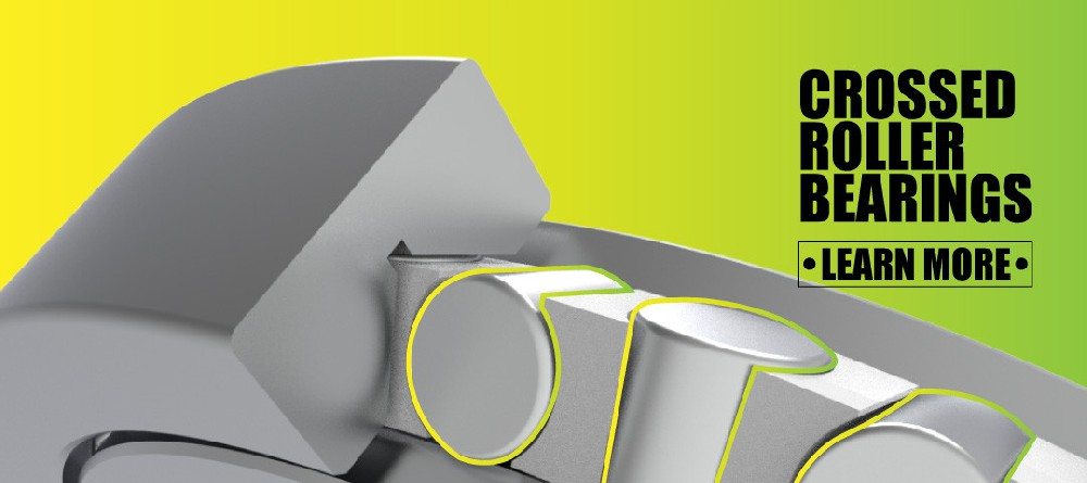
A cross roller bearing uses cylindrical rollers arranged alternately at right angles. One roller is positioned in one direction, while the adjacent roller is positioned perpendicular to it. This crossed arrangement allows the bearing to support radial loads, axial loads in both directions, and overturning moments.
This is why cross roller bearings are widely used in robot joints, rotary tables, medical equipment, radar systems, precision measuring machines, direct-drive motors, hollow rotary platforms, and harmonic reducers.
Unlike a typical two-bearing angular contact arrangement, a single cross roller bearing can provide a highly compact structural solution for multi-directional loading.

Why Cross Roller Bearings Offer Higher Rigidity
The most important advantage of a cross roller bearing is its ability to resist deformation under complex loads. Cylindrical rollers provide line contact rather than the point contact associated with balls. This generally gives a larger contact area and supports higher rigidity under load.
In a heavy load robotic joint, rigidity affects much more than bearing life. It directly influences:
– End-effector positioning accuracy
– Path repeatability
– Joint deflection under payload
– Vibration during rapid movement
– Robot settling time after stopping
– Gear-mesh stability in reducers
– Quality of welding, dispensing, cutting, inspection, or assembly operations
Consider an industrial robot carrying a welding torch or machining tool. If the wrist joint tilts slightly under an off-center load, the tool path may deviate. Even a small angular deflection can become significant at the tool tip because the error increases with distance from the bearing center.
Main Benefits of Cross Roller Bearings
For high-rigidity robotic joints, cross roller bearings provide several engineering advantages:
– Simultaneous support for radial, axial, and moment loads
– High rotational accuracy for precision motion systems
– Compact structure, reducing the need for separate bearing pairs
– Strong resistance to tilting and overturning moments
– High rigidity under changing robot poses
– Suitable for hollow-shaft and hollow rotary joint designs
– Useful for harmonic reducers, planetary reducers, DD motors, and rotary platforms
Thin-section cross roller bearings can also help designers reduce joint size and weight. This is especially relevant in collaborative robots, service robots, medical robots, humanoid robots, exoskeleton systems, and compact AGV-related mechanisms.
Cross Roller Bearing vs Angular Contact Ball Bearing: Load Comparison
The most meaningful comparison is not “which bearing has the higher load rating?” It is “how does the bearing react to the load spectrum of the joint?”
A robotic joint rarely sees only radial force or only axial force. It sees a changing combination of forces as the arm changes direction, orientation, speed, and payload position.
| Load Condition | Angular Contact Ball Bearing | Cross Roller Bearing |
|---|---|---|
| Pure high-speed rotation | Excellent choice | Possible, but must confirm speed and heat limits |
| Moderate radial load | Good | Very good |
| High bidirectional axial load | Requires paired arrangement | Well suited in one bearing |
| High overturning moment | Requires bearing spacing and robust structure | Naturally suited |
| Off-center payload | Can be effective with optimized support geometry | Often preferred |
| Repeated start-stop motion | Suitable with correct preload and lubrication | Highly suitable when rigidity is critical |
| Compact robotic wrist | May need several components | Often offers a space-saving solution |
| Hollow rotary axis | Depends on bearing arrangement | Frequently favorable |
| High shock or impact load | Requires careful verification | Strong option when correctly selected |
Cross roller bearings are usually preferred when moment stiffness is the dominant requirement. Angular contact ball bearings are often preferred when speed, low friction torque, and a conventional paired arrangement are the dominant priorities.
The Critical Difference: Moment Load in Robotic Arms
Moment load is one of the most underestimated factors in robot-bearing selection.
A robotic arm does not simply carry a load vertically. It moves the payload through space. The payload may be offset from the centerline. The robot may accelerate quickly, stop abruptly, rotate at changing angles, or experience process forces from welding, polishing, drilling, grinding, dispensing, or contact inspection.
As an application engineer, I would never select a bearing using only the rated payload of the robot. A 20 kg payload does not equal a 20 kg bearing load.
The real evaluation should include:
1. Maximum payload mass
2. Tooling mass and center of gravity
3. Offset distance from the joint center
4. Robot arm self-weight
5. Peak acceleration and deceleration
6. Cycle frequency and duty cycle
7. Process force, such as cutting or pressing force
8. Shock load from emergency stops or collision events
9. Ambient temperature and lubrication condition
10. Required positioning and repeatability target
For a cross roller bearing, the combined load capability can simplify the support design. For angular contact ball bearings, the support arrangement must be engineered so that both bearings share the load correctly.
When Angular Contact Ball Bearings Are the Better Choice
Cross roller bearings are not automatically the best answer for every robotic axis. In certain applications, angular contact ball bearings provide a more efficient and economical solution.
Choose a high-precision angular contact ball bearing when the design requires:
– High rotational speed, especially in motor-driven shafts
– Low friction torque and lower heat generation
– A controlled preload system with stable thermal conditions
– A conventional shaft-and-housing bearing arrangement
– Relatively low or manageable overturning moments
– High-speed angular positioning or reducer input support
– Compact paired bearings rather than one large rotary bearing
A servo motor shaft, high-speed tool-changing mechanism, compact spindle-type assembly, or reducer input stage may benefit from angular contact ball bearings. In these applications, the designer can use a matched pair, select the correct contact angle, and optimize preload for speed and stiffness.
For example, a robot’s high-speed motor input shaft may use angular contact ball bearings, while the output joint connected to a harmonic reducer may use a cross roller bearing. This mixed-bearing approach can balance speed, rigidity, cost, and packaging constraints.
When Cross Roller Bearings Are the Better Choice
A cross roller bearing is usually the stronger choice when the joint needs high stiffness in a compact envelope.
Select a precision cross roller bearing when the application includes:
– Heavy radial, axial, and moment loads at the same time
– Large payload offsets from the joint center
– High joint rigidity requirements
– Precision rotational positioning
– Rotary-table or turntable-type motion
– Hollow center design requirements
– Harmonic reducer output support
– Direct-drive motor integration
– Frequent start-stop operation
– Complex robot postures with changing load directions
Typical examples include:
– Industrial robot shoulder and elbow joints
– Robot wrist joints carrying off-center tools
– Collaborative robot rotary joints
– Four-legged robot leg joints
– Humanoid robot hip, knee, and ankle modules
– Medical imaging and surgical positioning equipment
– Radar antenna positioning systems
– CNC rotary axes and industrial turntables
– Precision inspection and measuring equipment
For a robot wrist carrying a gripper, camera, welding torch, or polishing head, the load is often offset and changes direction continuously. In this case, a thin-section or high-rigidity cross roller bearing can provide the stable support needed to maintain orientation accuracy.

Bearing Selection Procedure for Robotic Joint Designers
The most reliable selection process starts with the real load condition—not the bearing catalog.
Step 1: Define the Full Load Spectrum
List the maximum, minimum, and repeated loads during the full robot cycle.
Include:
– Radial load
– Axial load in both directions
– Overturning moment
– Rotational speed
– Angular acceleration
– Stop frequency
– External process force
– Shock loading
– Required service life
Do not rely only on nominal values. Use peak values and realistic safety margins.
Step 2: Calculate Dynamic and Static Conditions
Dynamic load determines fatigue life. Static load helps evaluate permanent deformation risk. Both are important in robotic joints because many robots repeatedly accelerate, stop, hold position, and experience intermittent shock.
A joint may rotate slowly but still face high static stress because of a heavy off-center payload. Conversely, a high-speed shaft may have modest load but require very low friction and controlled temperature.
Step 3: Set the Rigidity Requirement
Ask what deflection is acceptable at the end effector.
If the robot must maintain a precise tool path, bearing deflection must be considered alongside reducer torsional stiffness, arm stiffness, gearbox backlash, and frame rigidity.
A bearing with adequate life but insufficient rigidity can still cause poor machine performance.
Step 4: Review Installation Conditions
Even the best precision bearing can fail early if installation is incorrect.
Check:
– Housing bore roundness
– Shaft and housing shoulder accuracy
– Mounting-face flatness
– Bolt tightening sequence and torque
– Bearing preload method
– Cleanliness during assembly
– Lubricant type and quantity
– Seal design and contamination exposure
Cross roller bearings are precision components. Improper mounting can create uneven roller loading. Angular contact ball bearings are also sensitive to preload errors, especially at high speed.
Step 5: Validate the Design With Testing
For high-value robotic equipment, validate the bearing selection through prototype testing.
Monitor:
– Running torque
– Temperature rise
– Vibration
– Noise
– Positioning repeatability
– Bearing clearance or preload change
– Grease condition
– Wear particles
– Joint deflection under load
Testing should replicate the real motion cycle, not only a constant-speed bench test.
Practical Case: Heavy Load Robot Wrist Joint
Imagine a six-axis industrial robot with a wrist carrying a 15 kg tool assembly. The center of gravity is 250 mm away from the wrist rotation center.
Ignoring dynamic effects, the approximate gravitational moment is:
This is only the starting point. During acceleration, abrupt deceleration, or contact work, the actual moment can become significantly higher.
If the wrist must maintain high orientation accuracy during welding or inspection, the bearing must resist deflection under that changing moment. A cross roller bearing may simplify the structure because it directly supports radial force, thrust force, and overturning moment in one compact unit.
However, if the same system includes a high-speed drive motor upstream of the reducer, angular contact ball bearings may still be the better option for the motor shaft. The final design may therefore use both bearing types in different positions.
Common Selection Mistakes to Avoid
Several recurring mistakes can increase robotic joint cost and reduce service life.
– Selecting based only on bore diameter or outside diameter
– Comparing catalog ratings without comparing test conditions
– Ignoring overturning moment from offset payloads
– Using payload mass instead of total dynamic joint load
– Applying excessive preload to “increase stiffness”
– Ignoring heat generation at high speed
– Using insufficiently rigid housings or mounting flanges
– Failing to evaluate reducer, bearing, and housing as one system
– Neglecting lubrication and contamination control
– Choosing the lowest initial-cost bearing without lifecycle analysis
The bearing is part of the joint system, not an isolated component. The final performance depends on the bearing, reducer, motor, housing, seals, fasteners, lubrication, and assembly method working together.
Working With a Precision Bearing Manufacturer
For robotic-joint projects, a useful technical discussion should go beyond standard part numbers. The manufacturer should understand the application, load spectrum, accuracy target, installation space, and operating environment.
When requesting a quotation for cross roller bearings or angular contact ball bearings, provide:
– Bearing size constraints
– Inner diameter, outer diameter, and height limits
– Required load ratings
– Axial, radial, and moment load data
– Rotational speed and acceleration
– Accuracy class requirements
– Runout and rotational precision requirements
– Preload or clearance preference
– Lubrication method
– Operating temperature
– Corrosion, dust, vacuum, or clean-room requirements
– Expected annual volume and prototype quantity
Henan Yuwei Industrial Technology Co., Ltd. supports precision bearing applications across industrial robots, collaborative robots, SCARA robots, humanoid robots, service robots, medical robots, AGV systems, radar equipment, numerical-control machinery, industrial rotary tables, hollow rotary platforms, DD motors, harmonic reducers, and planetary reducers.
Its product range includes precision cross cylindrical roller bearings, high-rigidity cross roller bearings, thin-section cross roller bearings, double-row cross roller bearings, high-precision angular contact ball bearings, high-speed angular contact ball bearings, and long-life angular contact ball bearing series.
Final Recommendation
For heavy load robotic joints with substantial overturning moment, select a precision cross roller bearing when you need compact structure, high stiffness, multi-directional load capacity, and stable rotational accuracy.
For high-speed shafts and controlled paired-bearing arrangements, choose high-precision angular contact ball bearings when low friction, speed capability, and thermal behavior are the main priorities.
In many advanced robot designs, the most effective solution is not an either-or decision. It is a system-level combination: angular contact ball bearings for high-speed drive positions and cross roller bearings for the output joint where rigidity and moment capacity matter most.
If you are developing a robotic joint, harmonic reducer module, rotary platform, radar positioning system, or precision automation axis, share your working load data, installation drawing, speed range, and accuracy target with Henan Yuwei Industrial Technology Co., Ltd. A bearing selection based on real operating conditions can reduce redesign time, protect the reducer, and improve long-term motion stability.
FAQ
1. Can angular contact ball bearings support heavy load robotic joints?
Yes. Angular contact ball bearings can support heavy robotic-joint loads when they are correctly sized and arranged in pairs or multi-bearing configurations. However, for high overturning moments and compact joint structures, a cross roller bearing is often more efficient.
2. Why are cross roller bearings used in robot joints?
Cross roller bearings support radial loads, axial loads in both directions, and overturning moments in one compact bearing structure. Their high rigidity makes them suitable for robot wrists, reducer outputs, rotary axes, and joints with off-center payloads.
3. Are cross roller bearings suitable for high-speed rotation?
They can operate at moderate speeds, but their speed capability depends on bearing size, roller design, preload, lubrication, heat dissipation, and load. For very high-speed motor shafts, angular contact ball bearings are often the preferred choice.
4. What is the difference between a cross roller bearing and a crossed cylindrical roller bearing?
The terms are commonly used to describe the same general bearing concept: cylindrical rollers are arranged alternately at right angles between inner and outer rings. Specific structure, cage design, ring split configuration, and mounting method may vary by manufacturer.
5. How does preload affect a robotic joint bearing?
Preload removes internal clearance and can improve stiffness and positioning stability. Excessive preload, however, increases friction, heat, torque, and wear. The preload should match the actual speed, load, accuracy, and thermal conditions.
6. Can one cross roller bearing replace two angular contact ball bearings?
In some applications, yes. A cross roller bearing can often replace a paired angular contact ball bearing arrangement when the design requires compact support for radial, axial, and moment loads. The final decision must consider speed, load, installation space, stiffness, and cost.
7. What information should I provide when selecting a bearing for a robot joint?
Provide the radial load, axial load, overturning moment, rotational speed, acceleration, duty cycle, bearing space, target life, required accuracy, lubrication method, operating temperature, contamination exposure, and installation drawing.
8. Which bearing is better for a harmonic reducer output?
A cross roller bearing is frequently used at a harmonic reducer output because the position often experiences high moment loads, bidirectional axial loads, and strict rigidity requirements. The precise choice depends on the reducer’s bearing architecture and the robot’s operating conditions.
References
– [Henan Yuwei Industrial Technology Co., Ltd. — Precision Bearing Manufacturer]
– [Yuwei Bearing — About Super Precision Bearing Manufacturer]
– [Yuwei Bearing — Angular Contact Ball Bearing Manufacturer Guide]
– [Schaeffler — Rolling Bearings Technical Principles]
– [NSK — Angular Contact Ball Bearings]
– [THK — Cross-Roller Ring Product Information]
– [ISO 281:2007 — Rolling Bearings, Dynamic Load Ratings and Rating Life]
– [ISO 76:2006 — Rolling Bearings, Static Load Ratings]
Hot Tags: Cross Roller Bearing, Angular Contact Ball Bearing, Robotic Joint Bearings, Heavy Load Robot Bearings, Precision Cross Roller Bearings, Industrial Robot Bearings, Robot Arm Bearing, High Rigidity Bearings, Harmonic Reducer Bearings, Rotary Table Bearings