Content Menu
● Why Bearing Selection Matters in Collaborative Robots
● Cross Roller Bearing Construction and Strengths
>> Key Advantages of Cross Roller Bearings
>> Cross Roller Bearing Limitations
● Angular Contact Ball Bearing Construction and Strengths
>> Key Advantages of Angular Contact Ball Bearings
>> Angular Contact Ball Bearing Limitations
● Cross Roller vs Angular Contact Ball Bearings
● Which Bearing Is Better for Each Cobot Joint?
>> Elbow Joints
>> Wrist and End-Effector Axes
>> External Axes and Rotary Tables
● A Practical Bearing Selection Process
>> 1. Define the Complete Load Spectrum
>> 2. Set Stiffness and Deflection Limits
>> 3. Map Speed, Torque, and Thermal Limits
>> 4. Evaluate the Entire Support System
>> 5. Validate With Real Testing
● Expert Insight: Rigidity Is a System Requirement
● Common Selection Mistakes to Avoid
>> Choosing Only by Static Load Rating
>> Ignoring Overturning Moment
>> Overlooking Mounting Accuracy
>> Treating All Robot Joints the Same
● Recommended Choice for Collaborative Robots
● FAQ
>> 1. Can an angular contact ball bearing replace a cross roller bearing in a cobot joint?
>> 2. Why are cross roller bearings used in robot harmonic reducers?
>> 3. Are cross roller bearings suitable for high-speed robot wrists?
>> 4. What is the most important factor when choosing a cobot joint bearing?
>> 5. How does preload affect collaborative robot bearing performance?
>> 6. Are thin-wall cross roller bearings strong enough for lightweight collaborative robots?
>> 7. What information should be provided for bearing selection?
Collaborative robots demand compact joints that can move smoothly, stop precisely, and remain safe around people. When engineers compare an angular contact ball bearing vs cross roller bearing for collaborative robot applications, the central question is not simply which bearing is “better.” It is which bearing architecture best matches the joint’s real combination of speed, payload, overturning moment, positioning tolerance, available space, lubrication strategy, and expected service life.
For most cobot joints, cross roller bearings are the stronger choice when high rigidity, compact integration, multi-directional load capacity, and repeatable positioning are the priorities. Angular contact ball bearings are often the more practical choice when higher rotational speed, lower friction, lower cost, and a simpler high-speed drive arrangement matter most. The correct answer varies by robot axis and should be confirmed through load-spectrum calculations, structural analysis, and prototype testing.
Henan Yuwei Industrial Technology Co., Ltd. develops precision cross roller bearings and high-precision angular contact ball bearings for robotics, precision motion systems, radar equipment, machine tools, rotary platforms, harmonic reducers, planetary reducers, medical equipment, and other demanding applications. Based on practical bearing-selection work in robotic mechanisms, this guide explains where each bearing type fits—and where it does not.

Why Bearing Selection Matters in Collaborative Robots
A collaborative robot differs from a conventional high-speed industrial robot in several important ways. It commonly works close to people, handles frequent starts and stops, follows force-limited motion profiles, and may require lightweight arm structures. These requirements make joint compliance, backlash, vibration, friction, heat generation, and positional repeatability especially important.
The bearing is not an isolated component. It directly affects:
– Joint stiffness and end-effector deflection
– Positioning repeatability during pick-and-place, screwdriving, dispensing, and inspection
– Payload stability when the arm is extended
– Torque demand from the servo motor
– Transmission accuracy in harmonic or planetary reducer assemblies
– Safety performance during contact-sensitive operation
– Noise, vibration, and smoothness of human-facing motion
– Maintenance interval and total cost of ownership
A seemingly small angular displacement at the shoulder, elbow, or wrist can create a meaningful tool-point error. This becomes more noticeable when a cobot handles a long gripper, vision camera, welding torch, dispensing head, or inspection sensor.
For example, a bearing arrangement that permits excessive tilting under moment load may allow the robot flange to shift even when encoder feedback indicates that the motor has reached its target. In other words, the robot can be electronically accurate while mechanically less rigid than the task requires.
Cross Roller Bearing Construction and Strengths
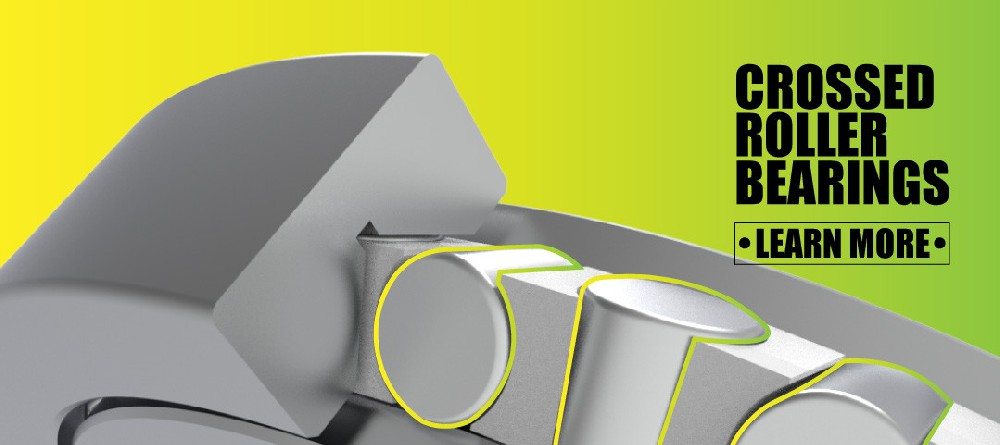
A cross roller bearing uses cylindrical rollers arranged alternately at right angles between the inner and outer rings. Neighboring rollers are perpendicular to one another, typically running in a 90-degree V-groove raceway. This geometry allows the bearing to support radial load, axial load in both directions, and overturning moment within one compact bearing assembly.
Unlike a conventional arrangement that may use two separate bearings to carry opposing axial loads and moment loads, a cross roller bearing can provide an integrated solution. This is a major reason why precision cross roller bearings are widely associated with robot joints, rotary tables, precision measurement systems, medical systems, and direct-drive rotary mechanisms.
Key Advantages of Cross Roller Bearings
High rotational rigidity. Cylindrical rollers offer a larger contact area than balls. Under equivalent installation conditions, this generally improves resistance to elastic deformation.
Multi-directional load support. A single bearing can accept radial, axial, and moment loads. This is valuable for robot joints where the payload center of gravity changes continuously as the arm moves.
Compact axial design. The integrated structure can reduce the space needed for a paired-bearing arrangement, supporting slimmer joint modules.
High rotational accuracy. The crossed-roller arrangement is designed for precision rotation. It is especially useful where tilt error, runout, or angular deflection must be tightly controlled.
Simplified joint architecture. In some robotic reducer and rotary-platform designs, one cross roller bearing can replace multiple bearing components, reducing interfaces and assembly variation.
Excellent fit for high-moment axes. Shoulder, elbow, base, and large payload wrist axes frequently benefit from the bearing’s moment-carrying capability.

Cross Roller Bearing Limitations
Cross roller bearings are not automatically the best solution for every cobot axis. Engineers should consider several trade-offs:
– Rolling friction may be higher than in a well-selected high-speed angular contact ball bearing arrangement.
– High rotational speed can increase heat, lubricant shear, preload sensitivity, and cage or separator design demands.
– Installation accuracy is critical; poorly machined mounting surfaces can distort the bearing rings and reduce performance.
– Preload selection requires care. Excessive preload may increase torque, heat, and wear, while insufficient preload may reduce rigidity.
– The initial purchase cost can be higher, particularly for high-precision grades and customized dimensions.
For collaborative robot manufacturers, the strongest cross roller bearing selection is usually one that balances rigidity and torque, rather than pursuing maximum rigidity without considering motor capacity and thermal behavior.
Angular Contact Ball Bearing Construction and Strengths
An angular contact ball bearing is designed so that the line of contact between the balls and raceways forms an angle with the radial plane. This contact angle allows the bearing to carry combined radial and axial loads. Depending on the required load direction and moment capacity, angular contact ball bearings are often installed in matched pairs or sets.
Common arrangements include:
– Back-to-back configuration (DB): High moment rigidity and good support spacing
– Face-to-face configuration (DF): Better tolerance of some alignment variation
– Tandem configuration (DT): Increased axial load capacity in one direction
– Duplex or multi-bearing sets: Used when higher stiffness, preload control, or combined loads are required
In collaborative robots, high-precision angular contact ball bearings are often considered for compact wrist modules, motor-side supports, belt-drive shafts, fast rotary tools, and other rotating assemblies where speed and low friction carry greater weight than maximum moment stiffness.
Key Advantages of Angular Contact Ball Bearings
Higher speed potential. Balls generate lower rolling friction than cylindrical rollers in many comparable applications, making angular contact ball bearings well suited to high-speed shafts and compact servo-driven mechanisms.
Smooth running torque. Properly manufactured and preloaded angular contact ball bearings can provide stable, low-noise rotation—important in service robots, medical robots, and human-facing collaborative systems.
Flexible arrangement options. Designers can tune axial stiffness and moment capacity by selecting contact angle, preload, bearing spacing, and paired configuration.
Cost-effective for suitable duties. Standardized bearing dimensions and well-established manufacturing methods can make angular contact ball bearings a cost-efficient solution for high-volume robot designs.
Useful in high-speed support positions. They are particularly suitable for motor shafts, high-speed end-effectors, spindle-like modules, and input stages where the primary demand is smooth, fast rotation.
Angular Contact Ball Bearing Limitations
The key limitation is that a single angular contact ball bearing does not typically provide the same all-direction support and overturning-moment rigidity as a cross roller bearing. To achieve a comparable level of moment resistance, designers usually need a paired arrangement and a suitable distance between bearings.
This may create challenges in compact cobot joints:
– More axial installation space may be required.
– Housing and shaft machining become more complex.
– Bearing matching and preload control are important.
– Assembly variation can influence joint stiffness.
– The total system may use more components, spacers, locking elements, and interfaces.
For a robot elbow or shoulder joint with significant cantilevered payload, a pair of angular contact ball bearings may be feasible, but it may not deliver the same stiffness-to-package-size ratio as a properly selected cross roller bearing.

Cross Roller vs Angular Contact Ball Bearings
| Selection Factor | Cross Roller Bearing | Angular Contact Ball Bearing |
|---|---|---|
| Rolling elements | Cylindrical rollers arranged alternately at 90 degrees | Balls running at a defined contact angle |
| Radial load capacity | High | High, depending on size and configuration |
| Axial load capacity | Supports axial load in both directions in one bearing | Supports axial load primarily in one direction per bearing |
| Overturning moment capacity | Excellent in compact packaging | Usually requires a matched pair and adequate bearing spacing |
| Rotational rigidity | Very high | Moderate to high, depending on preload and paired arrangement |
| Speed capability | Moderate to high, depending on design, lubrication, preload, and heat control | Generally favorable for higher-speed applications |
| Friction torque | Often higher than ball-bearing solutions | Often lower, especially for high-speed rotation |
| Installation space | Compact integrated support structure | Can require more space when using pairs or sets |
| Assembly complexity | Simple bearing count, but strict mounting accuracy required | More components possible; matching and preload are important |
| Typical cobot use | Main rotary joints, harmonic reducer outputs, high-rigidity rotary modules | Motor supports, wrist shafts, high-speed tools, compact drive modules |
| Relative cost | Often higher per bearing | Often lower for standard configurations |
The comparison should not be reduced to rollers versus balls. The real engineering comparison is usually:
One compact high-rigidity cross roller bearing
versus
One or more angular contact ball bearings plus spacing, preload, housing, and shaft support
That system-level comparison is where the design decision becomes clear.
Which Bearing Is Better for Each Cobot Joint?
Different robot axes experience very different loads. A six-axis collaborative robot does not need the same bearing solution at every location.
Base and Shoulder Joints
The base and shoulder experience the largest combined loads. They must support arm mass, payload mass, acceleration forces, and substantial overturning moments generated by a long reach.
A high-rigidity cross roller bearing is often the preferred solution for these locations because it can carry radial, axial, and moment loads in a compact structure. It is especially effective when integrated with a harmonic reducer output, hollow rotary platform, or direct-drive joint module.
Choose a cross roller bearing when the design requires:
– High payload-to-weight ratio
– Low angular deflection under reach
– Compact joint height
– Stable accuracy during acceleration and deceleration
– Strong resistance to external force disturbances
Elbow Joints
The elbow joint often experiences cyclic moment loading as the forearm extends and retracts. In collaborative handling, packaging, inspection, and machine-tending tasks, this axis may see many repetitions every day.
Cross roller bearings are commonly favorable here because the elbow needs both compactness and stiffness. However, a high-precision angular contact ball bearing pair can remain a viable solution if the joint has enough axial space and the duty cycle emphasizes speed over maximum structural rigidity.
Wrist and End-Effector Axes
Wrist axes often rotate faster and carry smaller loads than the shoulder or elbow. Their bearing choice depends heavily on the tool.
For a lightweight gripper, camera, or sensor, a high-speed angular contact ball bearing may offer the best balance of smoothness, speed, low torque, and cost.
For a wrist carrying an offset tool, precision dispensing head, force-sensitive screwdriver, or medical instrument, a thin-wall cross roller bearing can offer stronger resistance to tilting and external moment loads.
External Axes and Rotary Tables
Collaborative systems often include external linear slides, rotary positioners, inspection tables, and material-handling modules. Cross roller bearings are highly suitable for compact rotary tables, hollow rotary platforms, DD motors, precision indexing systems, and direct-drive applications where runout and tilting must remain low.
A Practical Bearing Selection Process
A reliable selection process starts with measured or simulated operating conditions rather than catalog dimensions alone.
1. Define the Complete Load Spectrum
Calculate or simulate:
– Maximum radial load
– Axial load in both directions
– Static and dynamic overturning moment
– Emergency-stop and collision load
– Acceleration and deceleration torque
– Load variation across all robot poses
– Tool weight and center-of-gravity offset
Do not select a bearing solely from the payload rating of the robot. A modest payload placed far from the joint center can generate a large moment load.
2. Set Stiffness and Deflection Limits
Define the allowable flange tilt, axial displacement, radial runout, and tool-point displacement. This transforms a vague requirement such as “high precision” into measurable targets.
For example, if a long tool amplifies small joint deflection, a high-rigidity cross roller bearing may be justified even if the nominal load is not unusually high.
3. Map Speed, Torque, and Thermal Limits
Compare the required joint speed with available motor torque. Preload, seal drag, lubricant type, and mounting distortion all influence running torque.
A high-speed wrist axis may favor an angular contact ball bearing because lower friction reduces motor heating. A slower but heavily loaded elbow axis may favor a cross roller bearing because stiffness has greater practical value.
4. Evaluate the Entire Support System
The bearing cannot compensate for a weak housing, thin flange, poorly supported reducer, or inaccurate mounting surface. Review:
– Housing wall thickness
– Mounting bolt pattern
– Ring support geometry
– Shaft and housing tolerances
– Reducer output stiffness
– Assembly preload method
– Lubricant access and sealing design
5. Validate With Real Testing
Bearing rating life calculations are necessary, but they are not the whole answer. ISO 281 provides methods for calculating basic dynamic load rating and basic rating life, conventionally associated with 90% reliability, while also addressing factors such as lubrication condition, contamination, and reliability in modified-life calculations.
For cobot joints, validation should also include:
– Running torque measurement
– Temperature-rise testing
– Position-repeatability testing
– Vibration and noise testing
– Static moment-deflection testing
– Emergency-stop cycles
– Long-duration endurance testing
– Lubricant-condition inspection
Expert Insight: Rigidity Is a System Requirement
A common mistake is to compare bearing catalog stiffness values without considering the complete robotic joint. In practice, joint deformation comes from several sources:
– Bearing elastic deformation
– Reducer torsional compliance
– Bearing-seat distortion
– Joint housing flexibility
– Fastener stretch
– Output flange bending
– Arm-link deformation
A cross roller bearing may improve the bearing-level rigidity, but the robot will only achieve its full benefit if the surrounding structure is designed to preserve that stiffness. Conversely, a carefully spaced and preloaded angular contact bearing pair may perform better than expected when supported by a robust housing and short load path.
The most effective approach is to treat the bearing as part of a joint stiffness budget. Allocate acceptable deflection across the reducer, bearing, housing, flange, and arm structure. This allows engineers to identify the true weakest link before increasing bearing size or precision class.
Common Selection Mistakes to Avoid
Choosing Only by Static Load Rating
Static load capacity is important, especially during collisions or emergency stops. But it does not reveal whether the bearing will deliver the required running torque, stiffness, speed, thermal stability, or fatigue life.
Ignoring Overturning Moment
Collaborative robot arms frequently carry offset loads. The moment load can become the dominant bearing-selection factor, particularly at the shoulder, elbow, and wrist.
Using Excessive Preload
Higher preload can improve rigidity, but it can also increase friction torque, heat, noise, and wear. The best preload is the one that meets stiffness requirements with an acceptable thermal and torque margin.
Overlooking Mounting Accuracy
Cross roller bearings and high-precision angular contact bearings require accurate shaft and housing geometry. Poor surface flatness, runout, or uneven bolt tightening can create internal stress and reduce expected life.
Treating All Robot Joints the Same
A cobot base, elbow, wrist, motor support, and end-effector spindle operate under different load and speed conditions. A mixed-bearing strategy is often the most technically and commercially effective solution.
Recommended Choice for Collaborative Robots
Choose a precision cross roller bearing when the robot joint needs high rigidity, compact all-direction load support, strong moment capacity, and stable positioning accuracy. It is particularly suitable for shoulder joints, elbow joints, reducer outputs, hollow rotary modules, precision rotary platforms, and offset-load wrists.
Choose a high-precision angular contact ball bearing when the application prioritizes high rotational speed, smooth operation, lower friction torque, and cost-effective paired-bearing support. It is especially suitable for high-speed motor supports, compact wrist shafts, belt-driven modules, and fast end-effector mechanisms.
For many collaborative robot platforms, the most effective solution is not choosing one bearing type for the entire robot. It is using cross roller bearings where structural stiffness governs performance and angular contact ball bearings where speed and low friction govern performance.
Henan Yuwei Industrial Technology Co., Ltd. can support bearing selection for collaborative robots with precision cross cylindrical roller bearings, high-rigidity cross roller bearings, thin-section cross roller bearings, double-row cross roller bearings, high-precision angular contact ball bearings, high-speed angular contact ball bearings, and long-life angular contact ball bearing solutions. Share your load conditions, joint drawing, speed range, accuracy target, and installation dimensions to evaluate a suitable bearing configuration for your robot platform.
FAQ
1. Can an angular contact ball bearing replace a cross roller bearing in a cobot joint?
Sometimes, but not always. A paired angular contact ball bearing arrangement can support combined loads and moments, but it often needs more axial space and careful preload control. For compact joints with high overturning moment and strict stiffness requirements, a cross roller bearing is usually the more direct solution.
2. Why are cross roller bearings used in robot harmonic reducers?
Robot harmonic reducers often need a compact output support that can carry radial load, axial load, and overturning moment while maintaining high rotational accuracy. A cross roller bearing can provide this integrated support and help maintain output stiffness.
3. Are cross roller bearings suitable for high-speed robot wrists?
They can be suitable, but the bearing must be selected specifically for the speed, preload, lubricant, seal arrangement, and thermal conditions. For very high-speed wrist rotation, an angular contact ball bearing may provide lower friction and better thermal behavior.
4. What is the most important factor when choosing a cobot joint bearing?
The most important factor is the complete load case, including overturning moment, not just payload mass. Also evaluate stiffness, allowable deflection, speed, duty cycle, installation space, and emergency-stop conditions.
5. How does preload affect collaborative robot bearing performance?
Preload reduces internal clearance and can improve stiffness and positioning stability. However, too much preload increases friction, heat, and wear. Preload should be selected as part of the complete motor-torque and thermal design.
6. Are thin-wall cross roller bearings strong enough for lightweight collaborative robots?
Yes, when correctly sized and installed. Thin-wall cross roller bearings are designed for applications that need compact dimensions with multi-directional load capacity and rotational precision. Their suitability depends on the actual radial, axial, and moment loads.
7. What information should be provided for bearing selection?
Provide the bearing envelope dimensions, shaft and housing design, radial and axial loads, maximum moment load, speed range, duty cycle, desired service life, lubrication method, accuracy target, allowable running torque, and operating environment.
References
1. [ISO 281:2007 — Rolling bearings: Dynamic load ratings and rating life]
2. [THK Cross-Roller Ring / Double Row Ring Product Information]
3. [Schaeffler: Cross Roller Bearings]
4. [Schaeffler: Load Carrying Capacity and Rating Life]
6. [Industrial Robots Demand Versatile Crossed Roller Bearings]
Hot Tags: Angular Contact Ball Bearing, Cross Roller Bearing, Collaborative Robot Bearings, Robot Joint Bearings, Precision Cross Roller Bearing, High Precision Angular Contact Ball Bearing, Harmonic Reducer Bearing, Industrial Robot Bearings, Robotic Arm Joint Bearing, High Rigidity Bearing