When an engineer specifies a bearing for a new machine, one number shapes almost every performance outcome: the contact angle. It determines how much axial load a bearing can handle versus radial load, how fast it can spin, how stiff it is under combined forces, and whether it will survive real-world operating conditions — or fail prematurely.
Yet for many buyers and even some engineers, the contact angle remains a somewhat abstract concept. You see it printed in catalogues — 15°, 25°, 40° — but understanding what it actually means, how it changes the physics inside the bearing, and how to select the right one for your application is where the real engineering value lies.
This guide breaks it all down: the geometry, the load distribution, the trade-offs between the three standard contact angles used in the 72 angular contact ball bearing series, and practical selection guidance you can apply today.
What Exactly Is a Contact Angle?
Before we compare 15°, 25°, and 40°, it is essential to understand what we are measuring. The contact angle of an angular contact ball bearing is defined as the angle between the line connecting the points of contact of the ball and the raceways in the radial plane — and a line perpendicular to the bearing axis.
Technical Definition: Contact angle (α) = the angle between the bearing radial plane and the resultant force vector through the ball-raceway contact points. Standard values for the 72 series: 15° (C suffix), 25° (AC suffix), and 40° (B suffix).
In a deep groove ball bearing, the contact angle is approximately 0° — balls are loaded purely in the radial direction. In an angular contact bearing, the inner and outer raceways are offset axially, creating a deliberate angle. This offset is what gives angular contact bearings their ability to simultaneously carry radial and axial (thrust) loads.
The greater the contact angle, the more the load line tilts toward the axis. This means a larger contact angle shifts capacity from radial load-carrying toward axial load-carrying. A smaller contact angle does the opposite — it keeps the bearing more radially dominant, improving high-speed capability.
The Geometry Inside the Bearing
Imagine looking at a cross-section of the bearing. The ball sits between the inner and outer raceways. In a standard deep groove bearing, the contact points on either side of the ball are at the same axial height — the force line is horizontal, perpendicular to the shaft. In an angular contact bearing, the outer raceway shoulder is raised on one side. This shifts the contact point upward, tilting the force line at angle α away from horizontal.
Because of this geometry, angular contact ball bearings must always be mounted in pairs (or in combination arrangements) when both axial directions need to be supported. A single bearing only supports axial load in one direction — the direction the contact line points.
The Three Standard Contact Angles: 15°, 25°, and 40°
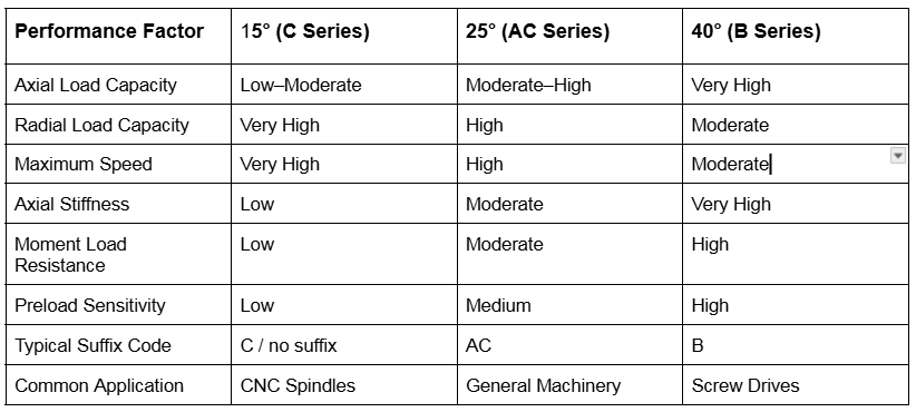
The 72 series angular contact ball bearings are manufactured with three standard contact angles, each suited to a different balance of speed, load capacity, and stiffness. Here is how they compare:
The 15° Contact Angle — Built for Speed
The 15° contact angle is the smallest standard angle in angular contact ball bearings. The shallow tilt of the load line means it stays close to the radial plane, giving this bearing its defining characteristics: exceptional high-speed performance and strong radial load capacity.
Why 15° Excels at High Speed
At high rotational speeds, centrifugal forces act on the balls, pushing them outward against the outer raceway. This increases contact stress and generates heat. A shallow contact angle reduces the effective load on the outer raceway contact under centrifugal conditions, which is why 15° bearings can achieve higher limiting speeds before temperature and fatigue become critical.
Additionally, the gyroscopic moment — the spinning moment of each ball about its own axis — is lower with shallow contact angles. This reduces internal friction and heat generation, extending grease life and overall bearing service life in high-RPM applications.
Limitations of 15° Bearings
The trade-off is axial load capacity. The relatively shallow load line means that any thrust force along the shaft axis creates a large radial component inside the bearing. The bearing can accept moderate axial loads, but under heavy combined loading — high axial and radial simultaneously — it is less capable than 25° or 40° variants.
Best Applications for 15° Bearings: CNC machining centre spindles | Grinding spindles | High-speed motor front bearings | Turbochargers | Dental handpieces | Precision milling heads
The 25° Contact Angle — The All-Rounder
The 25° contact angle represents the engineering middle ground. It balances radial load capacity, axial load capacity, and speed capability better than either extreme. This is why it is the most commonly specified contact angle across general industrial machinery.
Balanced Load Distribution
At 25°, the load line strikes an effective compromise. The axial load component is meaningfully higher than the 15° variant — roughly 40–50% more axial capacity — while speed capability only drops moderately. For machines where both shaft forces and thrust loads exist together (which is most rotating machinery), the 25° bearing handles the combined load case better than either extreme.
Back-to-Back vs Face-to-Face Mounting
The 25° AC bearing is frequently used in matched pairs mounted back-to-back (DB arrangement) or face-to-face (DF arrangement). The back-to-back configuration provides a wider effective span between contact lines, giving higher moment load resistance — essential in gearbox pinion shafts, conveyor drive units, and general purpose pumps.
Best Applications for 25° Bearings: Gearbox input shafts | Pump shaft supports | Electric motor drive ends | Light machine tool spindles | Agricultural equipment | Automotive transmissions
The 40° Contact Angle — Maximum Thrust Capacity
The 40° contact angle is the heavy-duty member of the angular contact family. The steep load line directs forces strongly along the shaft axis, giving this bearing the highest axial load capacity of the three standard angles — sometimes 60–80% higher axial capacity than a comparable 15° bearing of the same bore size.
High Axial Stiffness for Precision Positioning
High contact angles also deliver high axial stiffness. When a bearing arrangement needs to resist axial displacement under varying axial loads — for example, on a ball screw support or a precision linear axis — the 40° bearing deflects less per unit of axial force. This translates directly into better positional accuracy and reduced thermal growth effects in precision machinery.
Speed Limitations of 40° Bearings
The penalty for this axial strength is speed. The steep contact angle amplifies centrifugal and gyroscopic effects on the balls. At high RPM, contact stresses on the outer raceway rise sharply, heat generation increases, and fatigue life diminishes. The 40° bearing is therefore best suited to moderate-speed, high-load applications — not high-speed spindles.
Best Applications for 40° Bearings: Ball screw end supports | Heavy-duty pump thrust bearings | Worm gear shaft supports | Compressor axial thrust | Crane hooks and hoisting equipment | Propeller shafts
How Contact Angle Affects Load Capacity: The Numbers
To make this concrete, consider a 7210 AC bearing (50 mm bore, 25° contact angle) as the reference point. Here is how load capacity shifts when you change only the contact angle, keeping bore size constant:
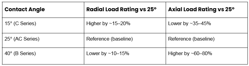
Important Note: These are approximate relative comparisons. Always verify dynamic (C) and static (C0) load ratings from the manufacturer’s datasheet for your specific part number.
Contact Angle and Speed: The Limiting Factor
Speed capability is one of the most critical differentiators between contact angles. The reference speed in bearing catalogues reflects the RPM at which the bearing, under standard test conditions, reaches its thermal equilibrium limit.
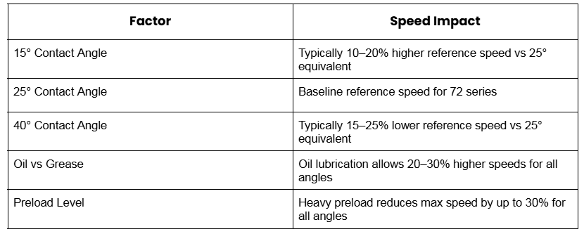
For CNC spindle applications in particular, the combination of 15° contact angle + oil-air lubrication + light preload is the standard formula for achieving speeds above 10,000 RPM on precision spindles. The 40° bearing simply cannot match this in a comparably sized envelope.
How to Choose the Right Contact Angle
Selecting the correct contact angle comes down to answering four key questions about your application:
- What is the ratio of axial to radial load? If axial load exceeds 30–40% of radial load, move toward 40°. If radial load dominates and axial is minimal or moderate, 15° or 25° is appropriate.
- What is the operating speed? High speeds (above 6,000–8,000 RPM for most 72 series sizes) favour 15°. Moderate speeds with mixed loading favour 25°. Low-to-medium speeds with heavy thrust favour 40°.
- Is axial stiffness or positioning accuracy critical? For screw drives, precision axes, or applications with tight positional tolerances, 40° delivers superior axial stiffness. For radial stiffness at high speed, 15° is preferred.
- What is the mounting arrangement? Back-to-back pairs: 40° gives maximum moment load resistance. Tandem arrangements for unidirectional axial load: all three angles work, but 40° gives highest thrust capacity. Face-to-face: 25° is most common.
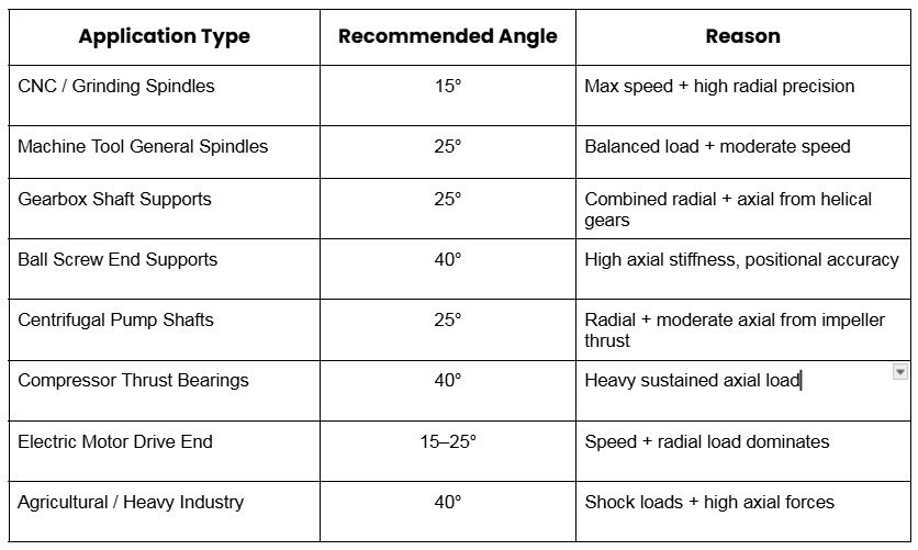
Quick Selection Reference Table
Reading the Suffix: How Contact Angle Appears in Part Numbers
When you look at a bearing part number in a catalogue or on a packaging label, the contact angle is encoded in the suffix. For the 72 series specifically, here is how to decode it:
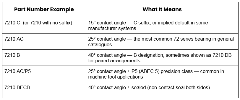
Pro Tip: SKF uses C / AC / B. FAG uses C / AC / B similarly. NSK may use A5 for 25° and A for 40° in some series. Always cross-reference with the manufacturer’s own catalogue when specifying critical applications.
Conclusion
The contact angle of an angular contact ball bearing is not a minor detail — it is the fundamental design parameter that defines what the bearing is capable of. Choosing 15°, 25°, or 40° is choosing between speed and thrust, between agility and strength, between precision positioning stiffness and radial load dominance.
The right choice depends entirely on your application. A CNC spindle running at 12,000 RPM needs a 15° bearing. A ball screw support holding a 5-tonne gantry table needs a 40° bearing. A general industrial gearbox is best served by the reliable 25° all-rounder.
Now that you understand the contact angle fundamentals, the next logical step is selecting the right size and specification within the 72 series for your specific bore, load, and speed requirements.